Yes, the output tubes needs much more voltage and I also have some doubts about the phase splitter´s ability to properly drive all those output tubes.
One more thing: There´s no negative feedback involved, so the output impedance and distortion would probably be quite high.
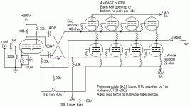
This is an inverted Futterman circuit, so in order to add feedback to the cathode of the input tube you must add another gain stage to get the correct phase.
A friend of mine breadboarded a similar circuit and he had some DC offset problems caused by the phase splitters current path through the output stage. Connecting the phase splitter´s negative side to ground instead of to the output solved the offset problems, but then everything went south signalwise.
There are other phase splitter topologies that doesn´t push DC through the output stage (LTP with some compensation circuitry).
One more thing: There´s no negative feedback involved, so the output impedance and distortion would probably be quite high.
This is an inverted Futterman circuit, so in order to add feedback to the cathode of the input tube you must add another gain stage to get the correct phase.
A friend of mine breadboarded a similar circuit and he had some DC offset problems caused by the phase splitters current path through the output stage. Connecting the phase splitter´s negative side to ground instead of to the output solved the offset problems, but then everything went south signalwise.
There are other phase splitter topologies that doesn´t push DC through the output stage (LTP with some compensation circuitry).
Hi,
@Fulling: Surely you remember Tim (forgot his exact moniker) who posted quite regularly here a few years back?
It's his schematic and knowing his background it should work OK, probably best on high Z high efficiency speakers.
I think he showed it just as an example of an alternate way to the classic Futterman when Joel (another member) was contemplating an OTL for his speakers.
The thread is either burried way deep or may well be in the archives by now.
Cheers,")
@Fulling: Surely you remember Tim (forgot his exact moniker) who posted quite regularly here a few years back?
It's his schematic and knowing his background it should work OK, probably best on high Z high efficiency speakers.
I think he showed it just as an example of an alternate way to the classic Futterman when Joel (another member) was contemplating an OTL for his speakers.
The thread is either burried way deep or may well be in the archives by now.
Cheers,
Hey I thought I beat you out of here, fdegrove.
I don't buzz around here much but friends do, and they occasionally bring things to my attention.
Of this circuit, it's designed to be within the tubes' limits. As such, you see only so much voltage and amperage in the load -- and yes, it would be much better in high-Z speakers, as all OTL amplifiers are by nature.
The circuit should work about as shown, but gain will be low, and you'll want gNFB on it. Even a 6AS7 looks like a pentode when you practically short the output with eight measly ohms (or even 16). Probably, an ECF86 or 6U8 or something like that would be suitable, using the pentode in pentode mode for high gain.
Tim
A friend of mine breadboarded a similar circuit and he had some DC offset problems caused by the phase splitters current path through the output stage
There is a very easy fix for this, just compensate for the offset current, connect one resistor from amplifier output to the negative rail, the resistor value can be calculated but it is easier to just test it out. I use this method in my own OTL and achieve an offset voltage of about 10mV which is also stable over time.
the output tubes needs much more voltage and I also have some doubts about the phase splitter´s ability to properly drive all those output tubes.
I agree with that there is enough voltage, there is no way to source enough current and give some useable output voltage with 60V, you probably need in the region of 140-160V.
However I am quite sure that the phase splitter can drive the output tubes, remember that the output tubes work as cathode followers meaning very low Miller capacitance and the split load phase inverter has a very low output impedance when symmetrically loaded, in this case about 350ohm so it shouldn't be a problem, in my own OTL the pole given by the phase splitter output impedance and the output tubes input capacitance is about 5MHz it will not be that high here but high enough.
Regards Hans
- Status
- This old topic is closed. If you want to reopen this topic, contact a moderator using the "Report Post" button.
- Home
- Amplifiers
- Tubes / Valves
- 6AS7 OTL