Hi all,
I saw this referenced by Sch3mat1c and wondered why everybody isn't using it http://pw2.netcom.com/~wa2ise/radios/6be6vol.html.
Basically it is a pot free volume control - no more nasty pots screwing up the sound - look at this thread on solid state using LDRs to see reports of the sonics of potless sound: http://www.diyaudio.com/forums/showthread.php?s=&threadid=80194
One advantage tubes have over LDRs is matching - the 6HS8 tube is a dual tube originally used in TVs (in the US) and the two sides are matched.
I intend to use it in a rebuild of a Rogers Amp (changing all of the circuitry) and so I bought some of these tubes.
Has anybody tried this and can you tell us something about it?
Any takers? As I bought surplus, I can supply some tubes at €1 a piece plus shipping.
Would like to compare build & test & results with others.
I just checked the first link above - seems to be broken - here's the correct one http://pw2.netcom.com/~wa2ise/radios/6be6vol.html look half way down the page
John
Would like to compare build & test & results with others.
I just checked the first link above - seems to be broken - here's the correct one http://pw2.netcom.com/~wa2ise/radios/6be6vol.html look half way down the page
John
Chris,
Are the THD levels to be found online? or do you mean that inmates have found this to be the case? or are you surmising that this is why they have not been used much before? or I should run the test?
English is so imprecise as a language
Unfortunately, I don't have the equipment or know how to do this.
John
")
Hi Analog,
I'm aware of this - I posted on the thread! The problem with this approach is that individual tubes are used for each channel & matching between channels is problematic - with the approach here one 6SH8 tube is being used for both channels with perfect matching between channels.
I also seem to remember that John Swenson couldn't live with the microphonics of this tube & put the BDT to one side last year but took it up again recently.
This was one of the lines of inquiry that led me to this tube & see here also http://www.diyaudio.com/forums/showthread.php?postid=887184#post887184 for John S views
John
The 6HS8 circuit is likely to have high distortion due to its use of varying output plate resistance Rp (versus G1 controlled current) for gain control. The actual signal will be varying this Rp too, so will cause distortion. This is likely to be OK for a 5 tube radio, but not for HI-FI. You could try to restore the linearity by using active counter- nonlinear loads in place of the plate pullup resistors, as in the long forgotten "voltage mirror" gain stage, or its latest re-incarnation as the "Aikido" input stage.
As for the Beam Deflection Tube approach, this was used by radio Amateurs in matched pairs successfully for SSB generation. There are simple tweek circuits published in QST for matching up the tubes (or eliminating the carrier signal for SSB). Main limitation here is the dynamic range of the signal on the deflectors.
One can also just use the classic two quadrant multiplier circuit (called the Gilbert cell in the four quadrant case). This is just a LTP with current sourced tail. The gain input controls the CCS reference and hence current. The LTP tubes above it would then be pentodes with resistive loads for the output.
Don
Hello John,
SSB is the abbreviation for single sideband radio modulation, a more efficient form of AM radio. QST is the name of the US amateur radio magazine, also a Ham radio codeword. Beam deflection tube designs for generating SSB modulation appeared back in the 60's. The balancing tweeks were just DC voltage adjust pots for the deflectors and a DC servo for balancing current partition between the two plates, used NE-2 bulbs in the feedback. (there are other concerns about magnetic fields in the environment and demagnetizing the tubes too. )
The voltage mirror idea is about using non-linear thermionic diodes (typically HV ones) for load resistors that cancel the 3/2's power law distortion of the pentode transfer characteristic. One can get similar results by using fixed or zero bias triodes for load resistors as used in the Aikido. (however the Aikido uses them for loading a triode gain stage, which is unnecessary to linearize)
To linearize the 6HS8 tube, one would want to AC couple the "linearizer" loads to the 6HS8 plates. Just DC coupling them would also correct out the gain control action.
Don
Don,
I'm afraid I'm out of my depth again (not an unusual condition for me). You seem to be saying that it may be possible to linearise the 6HS8 tube?
I don't understand how
Can this be simply explained on the circuit below? Sorry if I'm being a bore with this but I've ordered the tubes & want to try to make use of them
Thanks
John
I'm afraid I'm out of my depth again (not an unusual condition for me). You seem to be saying that it may be possible to linearise the 6HS8 tube?
I don't understand how
AC couple the "linearizer" loads to the 6HS8 plates. Just DC coupling them would also correct out the gain control action.
Can this be simply explained on the circuit below? Sorry if I'm being a bore with this but I've ordered the tubes & want to try to make use of them
Thanks
John
Attachments
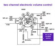
Well, I don't think there will be any easy way to do this. I would increase the 33K plate load resistors to look more like current sinks (maybe 330K) and connect them to say +400 Volts. Then capacitor couple each plate thru a series resistor to the cathode of a 2AV2 or 1V2 HV diode maybe. The diode plates connect to the +HV. The diodes then need something to draw some DC bias current, so will need high value resistors down to 0 Volts. (adjustable to get correct DC operating point) Will have to experiment with different resistors and currents to get good linearization (and hopefully not fry the diodes or 6HS8). One will really need a spectrum analyzer to monitor the distortion spectrum too (use sound card and FFT analyzer software). This will be quite a research project I'm afraid. Ideally one would try this on a circuit simulator first to get ballpark values, but good luck trying to find a simulator model for the 6HS8!
Another approach could be to use something like 6AL5 diodes in series with the 6HS8 plates to the existing 33K load resistors. (maybe a bunch of them in series) Output would come off the 6AL5 cathode to 6HS8 plate junction. Will require changing the 33K Ohm resistors to adjust amount of correction. A simpler circuit but less flexibility in adjusting. (Keep in mind the cathode to filament breakdown voltages of the diodes in all of these schemes too. Need separate filament power for them.)
edit: Oops, needs inductors across the diodes to keep DC gain variation currents out, then needs added constant DC biasing for the diodes. Worse than the other approach!
In theory one should be able to find a linearizing solution, but the amount of experimental work involved with the linearizer approach is a major obstacle.
Don
OK Don,
it's not easy - thanks for trying anyway. I'll probably guild the circuit shown and compare to existing 250K pot to judge it's sonic merits or demerits, as the case may be.
Offer stands for anyone who wants to experiment with these - will send one for the cost of postage.
Shoog, being an experimentalist - are you interested?
John
- Status
- This old topic is closed. If you want to reopen this topic, contact a moderator using the "Report Post" button.
- Home
- Amplifiers
- Tubes / Valves
- 6HS8 tubes for volume control