Hi all,
I was wandering around in my parent's neighborhood yesterday, and the wallet bited when I saw a garage sale. I came away with some power transformers and a choke. By using a DMM and a 12V AC source, I was able to figure out the secondary voltages; however, I am wondering there is any method to estimate the current rating of each of the secondary outputs?
Thanks,
There are a bunch of ways to determine the power ratting of the transformer....once you know the voltage ratios..ect...
You take a peek between the layers and see the wire gauges.. I can tell gauge # on sight from experience...and each gauge has an associated Circular Mills...Most wires in powers can be about 800 CM/ Ampere up to 1000 CM/Ampere....
Heater winding that are on the outside of the build can be as low as 500 CM/Ampere....
The other way is to load the secondaries and vary the load and let it sit for a few hours with a thermo-couple on the core, such as Fluke has one that plugs into meter...wait for the temp to stabilize ..you are loooking for 105 C, since this is most likely Class A insulation.... Then check the primary current and applied voltage for wattage ratting...
CHris
Measure the winding resistance. If you have a DVM and 1A power supply you can measure the heater windings (1 mV drop at 1A is 1 milliOhm. Figure one watt to three watts as the limit for copper loss per winding. Using 2 watts for example, I= sqrt(2/R). This a BALLPARK figure, but matches pretty well to transformers I've seen.
Thanks , Chris.
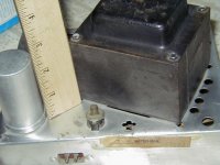
One of them looks like an organ power supply.
The PT is pretty beefy, a lot bigger than a Dynaco PA774A (for ST35).
It is about the same size as the ST70's PT!! See the picture. It has a
5V secondary which implies rectification by 5AR4, 5U4G etc. Since 5AR4
uses the least current, I can assume it won't get me in trouble if I drop in a 5AR4 ....
Attachments
Hi all
PCHW also mentioned he bought a choke, which I believe he wants to test as well... so my question is not off topic
I bought some HV chokes that are rated at 25H 'around' 100mA. How can I check for a more exact figure? I thought about using a LCR bridge across the choke and pumping in DC current with an adjustable CCS (PS with adjustable current) up to the point where the inductance starts to fall?!
Many thanks, Erik
- Status
- This old topic is closed. If you want to reopen this topic, contact a moderator using the "Report Post" button.
- Home
- Amplifiers
- Tubes / Valves
- Possible to estimate transformer specs?