Ok, here´s the story:
A couple of days ago I finished my first ever OTL amp, an SE piece with 4 x PL504 per channel in a choke loaded CF configuration with a very simple input stage and a bit of NFB.
It burns 200W to get 2x1W on the outputs, but the sound is actually quite marvellous. My speakers (FE 167E in 24L BR) doesn´t need much power or damping factor, they´re perfectly happy with a couple of watts and <10 ohms output impedance.
The SE beast has inspired me to build another OTL amp, something a little less controversial with slightly more output power. PP class AB, that is.
I´m thinking something like 4-6 6C19 per channel in a Totem Pole topology with +-150V rails and virtual ground.
1: What kind of phase splitter would do the job best with lowest parts count?
It stands between an inverted Futterman:
http://www.tubeaholic.com/projects/page.view?RowId=51
or this LTP-variation:
http://www.tubecad.com/january2000/page10.html
6C19 seems to require quite a bit of voltage swing, so I´m leaning towards the LTP for this reason.
2: Power supply... It takes quite a few different voltages to get an OTL working, but what concerns me is the +-150V high current supply for the output stage. I have a bunch of 1000uF 200V `lytics, four 112mH 2A chokes and a few suitable power transformers.
The problem is that I don´t have two identical PT´s, can I feed both channels from the same transformer?
My gut feeling tells me that this would cause problems since the PSU is floating with a virtual ground.
Buying two new power transformers is of course an option, but they don´t come cheap.
BTW: Before anyone starts arguing about the number of output tubes, remember what I wrote about my power and DF requirements.
I´ll probably build a high power, high DF monster OTL someday but not this time.
Cheers!
Hi ! I prefer the Kamijo topology very regular in testing , more than the futterman . (a 12BY7 is CCS of a pair twin triodes as splitter ) . The floating ground is a good solution that protects the speaker . Try the 6AS7g as they are very affordable and reliable from Russia (real mil spec stocks ) . I'll provide in a few weeks a full report on my new OTLs ")
Hi!
Already considered building a Circlotron design? I've made only best experience acoustically with my amp. But it turned out to be quite an immense project. I've presented it already during the thread "6C33 design comments" several weeks ago:
Uli's Circlotron
Although I use a low-ratio OPT (4:1, my first goal was output power), I think that with lower plate voltage and 4 (instead 2) power tubes per channel impedance could be lowered down to get "real" OTL service.
Good success!
Uli
Thanks for the replies.
After many hours of reading and calculating I begin to se the outlines of something:
PC86 input stage with CCS plate load cap coupled to a 2xPC86 LTP phase splitter. The balancing and hum cancellelation signals are fed to IRF820 followers on top of the phase splitters plate resistors.
B+ around 450V, 22k plate resistors, 10mA plate current through each PC86.
The "tail" goes to an SS CCS connected to a -60V rail.
Feedback goes from the amps output directly to the phase splitter´s inverting input, no global NFB to the input stage.
Output stage: 3+3 x 6S19 (russian low Rp triodes), +-160V and virtual ground.
Right now I´m waiting for PSU caps from the US, tube sockets from Ukraine and power transformers from Belgium.
Can´t do anything until I get at least the tube sockets...
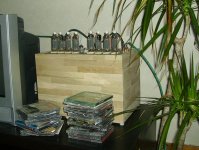

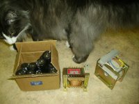
I´ve been quite lucky sourcing parts for my new OTL.
The PSU caps costed 5 bucks at Ebay and I´ve found toroid transformers with all the voltages I need except output stage B+ at local surplus stores.
This picture also show the reason I don´t want to use tubes with top caps, that cat costed more than the budget of this amp...
The PSU caps costed 5 bucks at Ebay and I´ve found toroid transformers with all the voltages I need except output stage B+ at local surplus stores.
This picture also show the reason I don´t want to use tubes with top caps, that cat costed more than the budget of this amp...
Attachments
I’m trying to educate myself on these OTL amplifier circuits and instead of creating a new thread I decided to revive this one as the title seems quite appropriate for questions…
The biggest headache I have in understanding these circuits is this one:
Feeding peak power of 25 watts to an 8-ohm load requires a current of about 1.77A and a voltage of about 14.14V. (I rounded the exact values). A typical push-pull OTL output stage is powered from a dual supply rail having about 180V per each side. This means 165.86V voltage drop across the tube during the signal peak (when feeding 25W to 8 ohms). Since 1.77A flows through the tube, the tube must dissipate 293 watts, right?
Most tubes suitable for OTL amps seem to have a maximum plate dissipation of maybe 30 watts. What is it that I don’t understand in this equation?
Couple of other questions:
Why the output tubes are not powered from a lower rail voltage as this would be the most logical solution to reduce the dissipation?
I understand the basics of the single-ended PI, Futterman and Technics variation of the Futterman and how these drive the output devices as various combinations of either cathode follower or common cathode. But, if the output stage is driven by a differential stage (e.g. http://www.audiodesignguide.com/otl/lee.html), how are the output devices configured then? Are both tubes acting as cathode followers – or just the tube at the top? Or am I completely lost? There is not much written about these differential driven circuits and TubeCad seems to be the only site discussing other stuff than various Futterman variations.
Yes. And paralleling output devices is also good for lowering the output Z. But for example, some of the designs out there claim 25W (I assume average) to 8 ohms and use only a single pair of 6C33C in push-pull. If my math is correct the claim for such output power does not seem realistic. Even if you had 8 6C33C in total (4 per each side) each tube would still dissipate about 73 watts - and that if the 25 watts to 8 ohms was the peak power rating! I’m wondering if I just have misunderstood something.
Efficiency goes up as you parallel tubes (up to a point). In transformer coupled the power potential doubles when paralleling. In an OTL it will quadruple the potential power output. This is because your current capability has doubled. Current is pretty much the limiting factor for OTL's with lower tube counts. Of course, overall power consumption is large with an OTL.
20Wrms is common power output with one pair of 6c33c in class AB. 80Wrms is common for two pairs in class AB. Your amplifier will consume twice as much with 2pairs but it will be putting out 4 times as much. Remember that the 6c33c's current rating of 600mA is continuous DC. Peak current is much higher, which is why class AB is the better route.
Most OTL manufactures claims are false. You can tell by the specs they are either lying about the power output or the fact it's class A (ok, maybe the first portion of a watt is).
SY said:If someone claims that they get 25W/8ohm in class A OTL from a single pair of 6C33, they are delusional.
True, but 2 x 6C33 in circlotron configuration in class AB it is quite possible.
I designed and built a 6 x 6C33 per channel pair of circlotron OTL amplifiers over 10yrs ago, the saga of which remains on my site to this day.
My amplifiers were a total flop, compound this with my then rapidly developing infatuation with SE and I ended up abandoning the project.
Don't get discouraged by my failure, knowing what I now know I could have got these to work well. In fact they went to a friend who did ultimately get them working. They were quite promising sounding, but several fried woofer voice coils and fireworks dissuaded me.
The high voltages are necessary because even close to saturation the internal resistances of most high perveance power triodes are at least 10X - 30X greater than your 8 ohm load resistance.
The nature of most music allows the tubes to operate at current levels that are inside of their continuous current ratings, and peaks which exceed it are generally of short duration. Testing however can create issues because although the amplifier might produce a 25Wrms output on a continuous basis the output tubes cannot dissipate the required power to do this safely for more than a few seconds.
A single 6C33 can handle continuous cathode currents in excess of 300mA, but dissipation should be limited to about 45W for good long term stability and reliability. PK currents can be as high as 7A for a couple of cycles - hence the ability to generate relatively large output powers on musical signals.
There are several guys here who hopefully will weigh in soon on OTL design and construction.. The 6C33 can be a very good choice for an OTL, but should be extensively burned in before use to assure good reliability. Also plate power should be delayed until the filaments are fully warmed up.
Higher impedance speakers make kinder loads and result in higher output powers. I recommend no less than 8 ohms, and 16 or 32 ohm drivers would be better, particularly in the bass.
My original design was intended to drive 5 ohm maggies, and was overly ambitious for my experience at the time. Start with something basic - a proven design would be best, there are enough pitfalls already.
Hi Jeb,
Sometimes I think I should embark on a little OTL - I do have a pair of 16 ohm Jensens which are one step above expendable so that could be fun..
The amplifiers in question sounded absolutely wonderful open loop, the triple differential driver topology and differential feedback never worked quite right even with balanced drive..
These amplifiers were the first clue that perhaps I did not need to use global feedback for linearity any longer.
The other problem was I just was not able to drive the 6C33 to the voltage levels required for full output. I never got beyond about 40Wrms output due to limitations in the driver design. I used direct coupled CF referenced to the outputs (cross-coupled bootstrapping the + supply to the CFs) which worked, but perhaps not that well.. The rest of it was based on 3 direct coupled high voltage LTPs which were very linear. (Talk about seesaw effect with the various loops closed, it totally unbalanced when I did so.) There was one pair of coupling capacitors in the whole amplifier. Overly complex, and probably (definitely) conceptually flawed. Sounded really good, missed target output power goal by >6dB..
True, but 2 x 6C33 in circlotron configuration in class AB it is quite possible.
Yes, absolutely. (see my post #12...
)- Status
- This old topic is closed. If you want to reopen this topic, contact a moderator using the "Report Post" button.
- Home
- Amplifiers
- Tubes / Valves
- OTL questions