barchetta said:Hey I have a question about this.. when we talk about resistors that are out of spec, can I determine if they are in spec by simply measuring them with no power applied? Or can they change while under power?
Depending on where they are in the circuit you may need to de-solder one end of any given resistor to measure it accurately. You always want to measure resistance with the power OFF. This is because the meter produces a small voltage and the meter measures the components resistance to it.
I guess what I am getting at is there are lots of them and I could easily measure then all quickly rather than having to replace them all.. I know many of you would say to me just replace them all.. but call me lazy..
Resistors don't pose the same level of failure risk as old caps. Replace the old caps, listen to some tunes and replace the resistors when you feel like it.
I did order some of the main caps last night.. have to hunker down and order all the disc type.. its exhausting looking all these up and making sure they will fit.
Please tell me you're not putting in more ceramic caps to replace the old... Some of those are interstage coupling caps and I'd replace those with something like 716P orange drop caps. Cheap and good sounding.
BTW- I have VERY little hum in my old preamp as it sits.. totally original.
Eico made good stuff. I have a pair of Heathkit WM-4 amps that sound GREAT, and I've heard the HF-81. Great amp.
anatech said:
I normally replace all resistors that have been overheated or changed colour not matter how they read. That may be most of them in some sets. No tolerance band gives you a 20 % tolerance, silver is 10 % and gold is 5 %. It would be very odd to see an original 5 % resistor in there. That was a precision resistor back then. If you have a 20 % resistor reading over 10 % off value, you may want to change it anyway. It's already heading off somewhere.
-Chris
Got it.. lifting one end is not hard either.. so I will do that with most of them.. seeing as mine is a preamp I doubt any of them got hot.. I do not recall seeing ANY discoloration at all inside this preamp. Oh goody; I have something to do tonight besides make my girlfriend happy. lol
anatech said:Hi BHD,
Change all the coupling caps, not just ceramic ones. Actually, ceramic coupling caps are normally safer that the tubular ones. They typically do not get leaky. They just sound awful. -Chris
Agreed on the coupling caps, those are the ones to replace with 716P orange drops.
Old electrolytics are the dangerous ones, if they're in the PS, they should be replaced with new electrolytics if you're not into the boutique parts thing.
716P type capacitors are the wrong ones. You can not install them in the same place the originals went because they are radial caps, you need axial types.
I don't know what you mean by this. You can definitely replace the coupling caps with the orange drops.
Hi tolerance resistors will not help you. Those circuits are designed with 20% parts in mind. Certain resistors should be matched together and not to a value.
Just because tubes are forgiving and CAN tolerate large variances, doesn't mean it's optimum. Carbon resistors can drift waaaaay out of tolerance in 50 years. I think that's one of the reasons that carbon resistors sound "warm", it's the tolerance variations and drift. But changing the resistors isn't nearly as critical as changing out all the capacitors.
So believe it or not Im finally getting to this! LOL.. been awhile..
If someone would be so kind I still have some questions.. I cannot locate the can cap with three caps in it.. the original is 20/40/40 UF... can I use a 50/50 can for the two 40's and then a 20uf or greater for the 20?? This is obviously in the power supply section...
Also.. I am told, if I am not using the phono section that it can be "disconnected" and hum will be lost.. Im hoping to make this thing a black hole of quiet.. although its stull functioning well with all orignal caps but the .1MFD caps replaced (did that a few years ago cuz it was easy and sorta wish I had kept those old black diamond caps)... there is some hum and popping.. but no hiss.
Im told refreshing the caps will not stop all the hum.. so since vinyl is not practical I would like to try disconnecting the phono section.. but where? and then how would I adjust voltage for tubes shut down (I read I need to do this.. not sure if its right).... My guess is I disconnect the X output at R59/C27?? I have no clue though.
Lastly.. and this is weird.. I was experimenting with using tape out.. WOW.. much better sound without the tone controls in place.. but I MUST use loudness as there is no bass (which I have modded BTW so the volume control works way up higher and accurate)... umm anyway while I was doing that my 400a threshold went bonkers and blew a fuse.. now no matter where I put the 400a on the Eico the meters go full bore and it blows a fuse.. however my little Aleph amp works fine.. I ran another preamp into the 400a and it plays fine.. so Im guessing I possibly have some DC on the outputs of the Eico that the 400a cannot tolerate or something like that??? Whats really odd to me is on the standard preamp section there are .25uf caps in series just before the RCA connectors and none at the tape out.. I thought the point of those was to ensure AC only... Not sure why Im second guessing these design as I have no clue what Im talking about.
Also.. are MICA caps ok for the ceramic replacements? My shopping cart is loaded up at mouser.. just need to pull the trigger..
here is the schematic..
Attachments
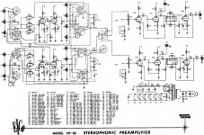
Barchetta -- using a 50/50 for the power supply is fine. The original Eico design of the HF-85 is woefully inadequate in B+ filtering, such that most stock units will exhibit a slight 120 Hz hum in the output as a result. Using a 50/50 uF will help, but the real answer is to split the 10K B+ dropping resistor into two 4.7K sections, and add another filter cap section in the middle where the two resistors join. Using a 50 uF for that position would be perfect as well.
The tape out jack is supplied by a .02 uF cap in the stock design. If these are not in place in your unit, you would surely have DC on the output at that point. If you are driving a SS power amp, from the tape out jacks, then I would increase the value of these caps to 1 uF, if VT equipment, then increase them to .1 uF.
In spite of increasing the value of these caps, the HF-85 has an eq error at the tape out jacks. This is because the fore mentioned coupling cap is connected directly to the plate of the line amp output stage, and not to the output of the coupling cap feeding the 33K FB resistor. This error results in a slight bass boost at the tape out jacks which you might find pleasant, but it is not accurate. To correct these issues, the tape out coupling cap should be increased in size as mentioned above, it should be tapped into the circuit at the output of the FB coupling cap, and then the FB coupling cap itself should be increased to 1 uF. These changes (along with the power supply changes) result in a very stable preamplifier, whose response at the tape out jacks is dead flat -- as it should be.
If you want to guild the lily, then a .25 cap (low voltage) should be placed between the output of the fore mentioned FB coupling cap, and the input of the tone stage amp. Then, the .25 uF cap on the main output of the tone stage amp can be dispensed with. The original design uses the .25 uF output coupling cap to prevent any DC at the main output, but such an approach leaves DC on the tone controls from the line stage, making the tone controls noisy when they operate. Inserting the new coupling cap as mentioned eliminates any DC on the tone controls from the line stage, and also eliminates the need for the main output coupling cap as well.
The excessive gain is a whole different story, that really requires a redesign of the line stage to reduce its gain, so that the level control will respond properly to most power amplifier sensitivities without the need to modify the level control to achieve it. However, the loudness control circuit should be modified so as to allow the sound level to remain relatively constant whether the loudness switch in turned on (providing bass boost) or off. The yahoo Eico group has details on this modification.
If you don't want to use the phono preamp tubes, the easiest thing to do is to just remove the them. Yes, it will cause the voltages to jump a little bit, but hardly to anything that is of concern. There is little if any need to compensate for the removal of these tubes if you chose to do so.
Good luck with your preamp!
Dave
The caliber of folks on this forum continues to amaze me.. Thanks so much for taking the time to reply with a thoughtful, and extremely informative post. While I dont fully understand it I'm going to read it a few times and google what I dont know.. however, most of it makes perfect sense..
I will say this.. I did do that mod of the loudness control you mention.. basically it involves swapping the resistor and cap on both channels of the loudness switch and then moving the tap wire from each potentiometer to the center position of the switch.. this effectively adds more resistance to the volume pots and lets you run them (the pots) up higher where they are much more controllable.. it used to be Id have to adjust the balance nearly every time I moved from a low volume to high volume ... now I do not and its much more linear for some reason.. I do need to run the loudness "on" to get bass but I suspect when Im done rebuilding I will not need to do this.. the loudness on puts a capacitor in each channel in I think series? with the potentiometers.. maybe not in series.. forget.. anyway.. they are both ceramic type but seem to be working after all these years. If anyone has this amp, all I can say is I wish I did this modification years ago.. I've spent way too much time manually putting the balance back and this is an easy mod for anyone who can use solder wick and solder.
If you do get a chance.. the one acronym I do not understand is the reference to "FB".. not sure what that is.. but I'll probably figure it out.. I would like to make that power supply mod you mention if I don't get it to go very quiet after the cap upgrades and removing the phono section by removing the two tubes as you suggest.. I was able to successfully recap, and re-transistor my Threshold 400a SS amp with a ton of help from this forum so I think I manage this based on what I learned...
I guess the hot ticket on this old amp is to change the tube heaters to DC... but thats beyond my level of capability... for now I'll keep it simple..
Time to make a capacitor order!
thanks again Dave...
I think it's best to keep the first PS cap after rectifier tube close to 20 maybe 30 max as bigger will stress that tube.
You might be able to put a choke or two in place or in conjunction with the R's in the PS right after the rect. to quiet things further! I think you just make sure the resistance of the choke is added to the resistors to give the same total resistance as before.
I don't know if you have room to do this, but you could also have separate PS chokes and associated resistors and caps branch off from the rect. tube for each channel. You would end up with a lot more capacitance and greater stereo separation I would think. Would even be quieter too. Somebody might know how to properly implement this if desirable. Edcor has some new low DCR chokes too. Maybe not enough space for all that too! Just a thought! A whole separate PS for each channel would be nice, but you would have to build a separate chassis. I have stock HF-12's with a similar preamp section. They aren't the quietest so I'm just thinking of mods. I've read of the disadvantages of the 12AX7's and wonder where maybe say 12AT7's could be subbed in for an improvement? I also think rebuilding PC1 & PC2 would help too as the resistors have probably drifted and it would be good to get rid of the ceramic caps there too. The HF-12 has them and I think they are all the same as the ones in the HF-81 of which there is a schematic of parts in them available.
Regards!
Randy
Last edited:
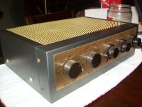
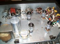
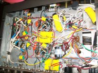
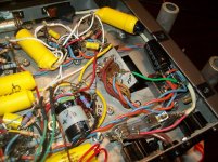
I converted mine to DC fils and haven't had any problems as far as PT overloading. This one was fairly rough, so a complete overhaul was a no brainer. I was able to retain and rebuild the selector, and the old pots work well after disassembling and cleaning, as do the RCA connectors in back. Pretty much everything else (except the tubes) is new. The only issues I had was straightening out the funky loudness resistor / cap wiring issue and a slight turn off pop that was corrected with a .02 1kv ceramic across the power switch contacts. Nice sounding little preamps for sure. I think you can see the low voltage full bridge and cap for the filaments in the last picture. I ran the wires twisted just in case the DC thing didn't work out.
Edit, after reading DCs post, I may have to revisit this project. Great thread.
Edit, after reading DCs post, I may have to revisit this project. Great thread.
Attachments
Last edited:
Rmyauck -- Your thoughts on keeping the first filter cap near its original value to maximize rectifier tube life is right on. However, in the case of the HF-85, the rule can be substantially relaxed, as the first filter cap does not connect directly to the rectifier tube, but rather, does so through a 2.2K resistor. Therefore, there is so much inrush current protection in place in the original design, that the first cap -- in this case -- can be elevated significantly will little concern for the rectifier tube's well being.
Thanks for bringing this topic up -- I should have addressed it directly in my original post!
Dave
Thanks for bringing this topic up -- I should have addressed it directly in my original post!
Dave
Randy -- As you mentioned, the first filter cap is the one to be careful of regarding size. More on that in a moment.
As for the rest of the filter caps down stream, their original size was typically based on a "big enough" standard, as in being big enough to produce an appropriately low impedance at each B+ distribution point, based on the needs of the circuit at any given point. The low impedance is necessary to perform three basic functions: (1) It continues the B+ filtering process to eliminate any power supply ripple from appearing on the B+ voltage, (2) It forces the output signal from each stage to be developed only across its load resistor (and not appear at the power supply distribution point as well), and (3) It therefore prevents any multiple stages connected to a common distribution point from interacting with each other -- either between stereo channels, or within a given channel.
Since the physical size of the electrolytic caps was rather large back in the day, the issue wasn't so much in going too big on these "down stream" caps when the original values were specified, but in using a value that was just big enough as a compromise between physical size and resulting performance. That's why the original value is typically the minimum size you would want to use, while today's higher capacitance levels in compact packages allow for greatly increased values to be installed in the same space. There are still practical limits as to size both physically and electrically of course in how big you can go, but for all intents and purposes, physical size falls out of the equation today, so that the point of diminished returns is usually reach when you have tripled the electrical size of the original down stream decoupling cap values. The effect of increasing their size is better definition and dynamics, particularly in the low frequency region.
Regarding the first filter cap -- and specifically when vacuum tube rectifiers are used -- the issue relates to the "hot switching" specification for the tube used. That is, the use of an excessively large first filter cap size is not at all about damaging the rectifier tube at routine turn on events. Under those conditions, the filament warm up time -- whether it is of the direct or indirectly heated type -- along with the DC resistance of the power transformer's windings provide virtually all the inrush current protection necessary with regards to protecting the cathode or filament of the rectifier tube. With hot switching concerns however, that relates to conditions where the the power is removed and then rather quickly reapplied (or "switched") with the cathode (or filament) still hot -- ergo the term. Under those conditions (we've all had rapid power line cycling events happen, haven't we?) the peak current impressed across the tube can be very large if the filter cap has significantly discharged itself during the down time, and the AC waveform is then reapplied at the peak of its crest. If the cathode is still hot under those conditions, it can be damaged instantly. Often, it is in fact during power line cycling events when many rectifier tubes fail because of this reason. Therefore, the tube manufacturer's recommendation for the size of the filter cap directly connected to the rectifier tube should be heeded. Further on down stream however, the comments given for those caps above apply.
Relating all of this to the HF-85 then, because of the significant resistance placed between the rectifier tube and first filter cap in this design, there is virtually no concern in raising the value of the first filter cap regarding hot switching issues. In this case, increasing it to 50 uF is just fine. The remaining caps then could easily be tripled in value or more for improved performance. In any event, it would still be a good idea to break the 10K B+ dropping resistor into two 4.7K sections as mentioned above. Using only a CRC (two stage) filter before the first audio tube supply point is marginal design for any vacuum tube preamplifier -- regardless of the size of caps installed. A three stage filter is best before powering the audio tubes, and it will be seen that Eico wisely corrected this design error in their followup preamp offering, the ST-84.
I hope this gives you a better understanding of the basic concerns regarding the HF-85's power supply design, and how you can best address them for improved performance.
Dave
I just realized that the modification I did to the loudness control last week was from a thread that Dave contributed too and was his description I actually used to make the change.. funny how things work in life.
Eico hf-85 volume pott - Page 3 - AudioKarma.org Home Audio Stereo Discussion Forums
The rest of this is very interesting and I'll probably play with some of this AFTER I do a stock rebuild. I think its important for ME to understand how the system performs in its stock form before I try and "improve" it.
The photos supplied help a "know enough to get in trouble type" like me understand and verify some things.. so I appreciate those being posted here.
I got mine out today and have decided to make some changes on it due to all this new info. I can't remember what size filters I used to re-stuff the can, but I do remember the ripple being quite low. I did add a 3hy choke in place of a resistor, but I can't remember what size cap I had in front of it. I will report my findings as soon as I tear back into it. I've been wanting to upgrade the signal wire for awhile anyway. A friend of mine just picked up his totally overhauled Ampex pre I was using today. I hated to see it go, but was very happy to see that he was pleased with it.
I'm especially interested in getting the DC off the tone controls and eliminating the output caps. Thank you very much for taking the time to type all that out DC. It is much appreciated by this old solder slinger. I wish I could contribute something in return.
I'm especially interested in getting the DC off the tone controls and eliminating the output caps. Thank you very much for taking the time to type all that out DC. It is much appreciated by this old solder slinger. I wish I could contribute something in return.
All parts have arrived.. I started with the first capacitor... the .03MFD what I believe is called a choke? Is that correct? Anyway.. the pyramid that I replaced with an orange drop .033MFD cap is totally open.. I cant get it to charge at all with a multimeter.. No difference in hum or noise.. however, while its likely wishfull thinking I seem to hear more definition in the highs.. Next I'll be tackling the can with three caps.. I may go right to Daves advice and add a 4th cap by splitting up the 10k resistor.. depends how nutty Im feeling at the time I go in.. ")
I swear more definition... listening now.. lol.. probably not.. Its amazing how good it sounds with all these old caps.. cant wait to get them replaced and listen..
By the way... the loudness control modified as mentioned earlier is not in the least bit muddy using the tape out jacks (which is what I will always use going forward.. no need for tone control at this time and I dont have any intention of dealing with those two resistor/cap packs on each tone control..) When done I'll probably fiddle with the caps on the loudness controls to get the right bass for my speakers/room.. although as of right now they are just short of perfection.
Sounds like you are on the right track. I think I would definitely add the extra capacitance as suggested by DC. Nothing better than a stone cold quiet tube pre.
Yes, I've decided to just do it and be done with it
Solder iron heating now.. I'm a little concerned about the orange drops I bought now.. they are 600v and quite large.. especially the .25MFD replacements... I had planned on replacing the .02MFD caps on the last stage of the tape section with the .22MFD orange drops (again this is something I read DC suggest to bring the bass up) to eliminate the use of the loudness switch... They are pretty gi-normous caps..
Thoughts? are there orange drops with less V? I bought all my parts from a place calaled tubedepot (tubedepot.com)... very reasonable prices compared to mouser...
- Status
- This old topic is closed. If you want to reopen this topic, contact a moderator using the "Report Post" button.
- Home
- Amplifiers
- Tubes / Valves
- HF-85 Rebuild advice