Is there a good rule of thumb for determining the optimal relationship of an output transformer's primary impedance to plate resistance in a push-pull circuit?
And, if you connect an 8 ohm load to a 4 ohm secondary, do you get the same doubling of the primary as with a single ended transformer, or is there a different relationship?
And, if you connect an 8 ohm load to a 4 ohm secondary, do you get the same doubling of the primary as with a single ended transformer, or is there a different relationship?
I would totally agree with SY and second what he says....
There are "rules of thumb" but they are really not usefull unless you were stranded on a deserted island trying to make a radio from scrap parts laying around..Now if you were deserted with 10 georgous hot women, then you make sure to NOT get the radio to work")
One common misunderstanding i hear alot... Is that a partiuclar plate load goes with a particular tube type.... A good plate load depends heavily on the operating conditions of the tube...There is what is refered to "optimum plate load" ...... Arriving at this requires reviewing the plate curves and fitting a load-line to get the best power output for the best linearity.....
One rooky mistake i see all the time with deriving plate loads..is using the wrong plate curves with pentodes/beam tubes... You need to make sure you are using the curves for the correct SCREEN VOLTAGE....It is not uncommon to see mostly 250V for the screen voltage in many data sheets.....
The other big mistake is using idle voltages to derive the plate load.... For example you have an amp with 490V on the plates and 485V on the screens when idleing... When the amp is turned up to max clean sine-wave signal output, say 100W, the Plate voltage may be at 430V and the screen volts may be at 400V...
That is the target voltage you design to.....
The power supply in most amps is not regulated, so plan on designing with the voltages and full power output....then assume the voltage will raise above these values at idle, which is really not of much concern at idle....
Chris
There are "rules of thumb" but they are really not usefull unless you were stranded on a deserted island trying to make a radio from scrap parts laying around..Now if you were deserted with 10 georgous hot women, then you make sure to NOT get the radio to work
One common misunderstanding i hear alot... Is that a partiuclar plate load goes with a particular tube type.... A good plate load depends heavily on the operating conditions of the tube...There is what is refered to "optimum plate load" ...... Arriving at this requires reviewing the plate curves and fitting a load-line to get the best power output for the best linearity.....
One rooky mistake i see all the time with deriving plate loads..is using the wrong plate curves with pentodes/beam tubes... You need to make sure you are using the curves for the correct SCREEN VOLTAGE....It is not uncommon to see mostly 250V for the screen voltage in many data sheets.....
The other big mistake is using idle voltages to derive the plate load.... For example you have an amp with 490V on the plates and 485V on the screens when idleing... When the amp is turned up to max clean sine-wave signal output, say 100W, the Plate voltage may be at 430V and the screen volts may be at 400V...
That is the target voltage you design to.....
The power supply in most amps is not regulated, so plan on designing with the voltages and full power output....then assume the voltage will raise above these values at idle, which is really not of much concern at idle....
Chris
Agree with what you guy's are saying (to a point) but doesn't the tube
it'self and it's plate resistance have a large factor in determining the load?
Take an el84 or a 6v6, most if not all trafos used are in the 8k to 10K
range with wildly different operating points. Most KT88 amps are in the
4k to 5k range and 6l6's are generally built around 6600 outputs.
If it was only operating point that determined it why the usual suspect
load trafos associated with these tubes?
Not questioning here, just want to learn the reasons if you would.
You can get too hung up on determining optimum anode loads, but for triodes you won't usually be too far away from twice ra at the operating point. For pentodes you definitely have to resort to curves, ruler, and pencil. Remember that the output transformer simply reflects what it sees on the secondary, so unless you have loudspeakers that are pure resistances (very rare) your anode load varies by a factor of two over the audio range anyway.
kegger said:Agree with what you guy's are saying (to a point) but doesn't the tube
it'self and it's plate resistance have a large factor in determining the load?
. . .
Indeed, but working on plate curves inherently includes that parameter . . . among many other
Yves.
Hello,
My opinion is... efficiency. Many different tubes can drive same load, i.e. same OT with sampe load. But this not imply any of them lead to full maximum efficiency. An 807 PP can drive barely a 10,000 Ohm anode to anode load in class AB1. A KT88 can drive, in the same circuit a 4,000 Ohm anode to anode load. A KT88 can drive 10,000 Ohm load same as 807. So, what makes the difference? Efficiency, as to say more power at the same distortion level per power consumed.
A KT88 driving a load of 4KOhm offers greater amplification becouse of less transformer difficulties.
Regards.
Larry.
Many of the recomended plate loads in tube manuals are completely off the mark... Must have hired interns to do some of that stuff...
The 6.6K you commonly see with 6L6 tubes refers to Ultra-Linear connection...at a specific operating condition....
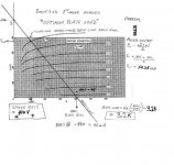
Here is a image to setting up a Class AB1 KT66 Push-Pull load line for 400V screen and 410V on the plate.... i goofed on one number in there but it's very close.... You want the load-line to extend only up to the 0-bias curve becuase not interested in going Class AB2.....
You want to stay in the saturation region of the curves in order to maintain the plate resistance as much as possible, very important for frequency response...if you make the load line to steep then you loose voltage swing and you spend too much averaged time per cycle over the MAX plate dissipation and the tube could red-plate.... If you make the plate load to big then you intercept the 0-bias curve when it is in TRIODE region, which reduces your current swing as well as causes the tube to clip sooner, you also draw excessive screen current and the plate resistance drops down very low to where the tube behaves like a triode....now this low plate resistance will completly alter the frequency response......
The key thing with this curves is that they are for 400V screen voltage.....if you are using a different screen voltage then you need a totally different set of curves, which will produce different end results....
Chris
The 6.6K you commonly see with 6L6 tubes refers to Ultra-Linear connection...at a specific operating condition....
Here is a image to setting up a Class AB1 KT66 Push-Pull load line for 400V screen and 410V on the plate.... i goofed on one number in there but it's very close.... You want the load-line to extend only up to the 0-bias curve becuase not interested in going Class AB2.....
You want to stay in the saturation region of the curves in order to maintain the plate resistance as much as possible, very important for frequency response...if you make the load line to steep then you loose voltage swing and you spend too much averaged time per cycle over the MAX plate dissipation and the tube could red-plate.... If you make the plate load to big then you intercept the 0-bias curve when it is in TRIODE region, which reduces your current swing as well as causes the tube to clip sooner, you also draw excessive screen current and the plate resistance drops down very low to where the tube behaves like a triode....now this low plate resistance will completly alter the frequency response......
The key thing with this curves is that they are for 400V screen voltage.....if you are using a different screen voltage then you need a totally different set of curves, which will produce different end results....
Chris
Attachments
I hear what some are saying but it looked to the general public until I
posted that only the voltage and or current were responsable for load
and the plate resistance of the tube it'self had no factor in it.
If you ran a 6V6, 6L6, KT88 all in UL at the same plate voltage, current
then we'd have different optimal loads correct? One determining factor
would be the plate resistance of the tube it'self?
And the load would go from high to low starting with 6V6 then 6L6 onto
KT88 and at least partially because of there plate resistance?
kegger...
Regarding Plate resistance.....
If you look at the curves in my last post.....
The KT66 curves.....
The plate resistance is the SLOPE of the curves in the saturation region.....
The flatter they are the higher the plate resistance...so refering to these curves, if you visualize these regions changing thier slope...it has no bearing on the load-line....
When the plate resistance changes...it effects the frequency response of the OPT.... Since when INDUCTANCE is calculated, leakages, winding capacitances also are calculated based on Plate load and plate resistance....
The reason for all the analysis with deriving load-lines is because tubes are NON-LINEAR...if tubes were LINEAR devices than plate load would be trivial and could be done with a simple first order equation, without needing to see the curves.....
It is a lot of work, but i can convert the curves into polynomials and create a closed form non-linear equation of the plate curves that is very acurate..then designing accurately from just equations is a simple task...
Chris
I hear yu and have the concept of drawing the load lines down.
But as I said a lot of this stuff may be to technical for some to grasp
and will just try an "read between the lines" where it can look like a
plate resistance on a tube has no bearing on the load.
I'm not saying the plate resistance doesn't change with operating point
or that our load is steady at all but if the plate resistance of a tube is higher
then another (by some certain margin) does it not make our optimal load higher? (in general terms)
I'm not trying to deminish the merrits of very technical answers at all
but think that non technical ones can coexist with them and maybe help
more people in the broad scheme of things then the purely technical ones.
My thoughts on it anyway. Could be way off but that's me.
but think that non technical ones can coexist with them and maybe help
more people in the broad scheme of things then the purely technical ones.
My thoughts on it anyway. Could be way off but that's me.
kegger...
When dealing with pentodes/beam tubes....
The plate resistance is not directly corelated with optimum plate loading...
In Fact when a pentode goes higher in plate resistance it is approaching being an ideal pentode, ie, getting closer to a ideal current source...
i can prove this to you graphically so you can see first hand without any technical over-kill... I can show various optimum load-lines with different tubes and different operating conditions..
Chris
If you'd like to do that I'd surely be interested in seeing it.
I know sometimes advice/sharing can be more of a pain then it's worth
but if someone including yourself wants to share further I'm up for learning.
If it's to much work I understand that as well, we all only have so much time.
I know sometimes advice/sharing can be more of a pain then it's worth
but if someone including yourself wants to share further I'm up for learning.
If it's to much work I understand that as well, we all only have so much time.
Thanks for all of the suggestions. My application here is actually a little goofy. My interest is in comparing various methods of driving my headphones (32 ohm Grados). I've been doing single ended and enjoying it quite a bit, but I thought a push-pull circuit might be interesting to try too.
I was thinking about using one of the super cheap Edcor push pull output transformers (http://www.edcorusa.com/products/transformers/xpp/xpp10-16-8k.html) and both halves of a dual triode, like a 6SN7 or a 6H30 in push pull. The concern, then, is that the plate resistances of these tubes is very different, so I am really just seeing if either is a better choice based on this criteria. In the end, I have, and will probably try, both, but I am just curious about the why.
-d
dsavitsk, as the discussion has shown, picking a load impedance with pentodes is tricky stuff. Fortunately, you're interested on triodes. My rule of thumb for triodes is simple: the higher the load, the better the sound. Higher loads will yield less power (lower efficiency,) but you're driving headphones so efficiency is pretty much irrelevant. Might as well trade efficiency for better sound if you have no need for the power.
The rule of thumb begins to fall apart when you are using an output transformer to couple to the load and you try to use a transformer with a really high winding ratio (primary impedance) simply because it's more difficult to make a really good 20k transformer than an 8k.
I'm not personally familiar with the Edcor transformers, so I can't make a specific suggestion, but if it were me I would probably consider the highest primary impedance they offer in the power/DC current category you are looking at.
-- Dave
- Status
- This old topic is closed. If you want to reopen this topic, contact a moderator using the "Report Post" button.
- Home
- Amplifiers
- Tubes / Valves
- push-pull and primary impedance