I have been attempting to adapt a design by Thorsten Loesch called the "Full Monkey Amplifier" to use a 5687 and a 12B4A instead of a WE 437A and a 300B. Trying to figure out the values for the biasing resistors is turning my brain to tapioca. The problem is that the old argument about which direction current flows very much comes into play in this topology. I have tried to find the diagram of the amplifier that I came across while doing research on calculating ultrapath capacitor values but I have been unable to find it again or find it by googling for it. Basically the voltage values given at different points in the circuit seem to contradict Ohm's Law. I can think of only three possibilities of why this is: 1) I am wrong. 2) Thorsten is wrong. 3) Thorsten muddied the water for his own reasons. I suspect that #1 is a winner in this case. If anyone has a image of the circuit that they could post, it would be greatly appreciated. Otherwise someone gracious enough to help me will not have anything to refer to. Many thanks in advance for any help.
G said:I invite the members here to check the listed voltages and see if it makes sense to them.
It does make perfect sense. There is about 15 V drop on the choke. Think currents. Total current (80mA) passes through the transformer , 300B and 820 Ohm (voltage drops by 65V from 240 = 175V at the top of 3K9 resistor) - after that it is split two ways: 36 mA goes through the choke and 437A, the rest (44mA) - through 3K9. Both currents combine at 25 Ohm resistor, where 80 mA creates 2V drop.
Cheers
Alex (x-pro)
x-pro said:
It does make perfect sense. There is about 15 V drop on the choke. Think currents. Total current (80mA) passes through the transformer , 300B and 820 Ohm (voltage drops by 65V from 240 = 175V at the top of 3K9 resistor) - after that it is split two ways: 36 mA goes through the choke and 437A, the rest (44mA) - through 3K9. Both currents combine at 25 Ohm resistor, where 80 mA creates 2V drop.
Cheers
Alex (x-pro)
Thanks for the reply. I just needed to simplify the circuit one more step to see it. I will draw up the circuit using the 5687 and 12B4A and post it tommorrow or the next day. Just to make sure I got it right.
5687 has a lot less mu than the 437 iirc, I would try 6c45, or even c3a ..I think pentode run as triode, they are pretty much drop in.
I don't think our friend T will return to diy, that guy put in 1000s hours, he's sorely missed, but perhaps burned himself out, and you couldn't expect taht kind of help from anyone.
I don't think our friend T will return to diy, that guy put in 1000s hours, he's sorely missed, but perhaps burned himself out, and you couldn't expect taht kind of help from anyone.
This design makes since if you think of the DC and AC conditions seperately. I am at work now, so I have no ability to post diagrams but you can draw your own. It is often easier with circuits like this to draw two diagrams. one for DC, and one for AC. All capacitors are assumed to be a short circuit for AC. It is often easiest just to assume that the DC conditions are magically satisfied and ignore them for the AC case. The power supply is also assumed to be a short for AC. To analyze the DC path, ignore (they are open) all capacitors, they (ideally) don't exist for DC.
note:
I have developed the lazy attitude that current flows in the direction that makes the particular circuit easiest to understand. It makes no difference as long as you are consistent within a given circuit. I guess that I have lived in the SS world too long.
For the AC case, this amp looks like any other two stage amp. The 820 ohm is the cathode bias resistor for the output tube. The 25 ohm is the cathode bias resistor for the input tube. Ignore the 3.9 K resistor for the AC case, it is bypassed and can be considered part of the power supply. Because this amp has a unique "power supply" arangement no coupling cap is needed. Both tubes are wired in an "ultrapath" arangement which means that the 47 uF caps are in the signal path and must be of high quality, think motor run caps.
The DC case is a bit unique. Both tubes are wired in series across a high voltage power supply. This is done to eliminate the coupling cap. There are two large caps (the ultrapath caps) in the signal path, but these are present in a "normal" design anyway. Mr Kirchoff proposed that all current paths in a series circuit MUST pass identical currents. Actually it is the SAME current since there is only one entry point and one exit point to a series circuit. No one has yet to prove Kirchoff wrong. Now if we want to wire two devices in series that inherently want to draw different amounts of current (a big tube and a small tube) we must provide a path for the excess current to flow around the small tube. That is the purpose for the 3.9 K resistor. 80 mA enters the 300B through the output transformer. It leaves through the cathode and all 80 mA flows through the 820 ohm cathode resistor. Now if all 80 Ma were to flow through the 437A, it would have a short unhappy life, so we provide two paths for current to flow. The 437a circuit, and the 3.9K resistor are in parallel. 36 mA flows through the 437A, and 44mA flows through the 3.9K resistor. The two paths again join, and all 80 mA flow through the 25 ohm resistor. Assuming no grid current no current flows through the 47K resistor, there is only one path for current through this amp.
If you are trying to modify this design, you must consider the DC case first. Since there are 3 seperate circuits, the 300B, the 437A, and the 3.9K resistor, and they all interact, it will be an itterative process. It is rare that real tubes actually match the published data sheets, so expect to do some tweeking to get the DC right before even expecting sound from this amp.
Alex answered the question well, but before reading his answer I drew the current paths and resultant voltages on the schematic. I've attached a scan here to help you visualize it.I just needed to simplify the circuit one more step to see it.
Attachments
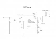
Thank you all so much for your replies. They were very helpful. Below is a diagram of the amplifier I would like to build. I believe it is correct but I do have a couple of questions. The voltage drop across R2 is not 23v but four volts. Since I want the grid of the 12B4A at -23v and it has 150 on it because of the direct connection to the plate of the 5687 I needed the cathode of the 12B4A to be 23v higher than the grid so 7v + 162v + 4v = 173v or 23 volts higher than the grid. I do think I am looking at this wrong though. I think I need to drop 11v across R2. R3 is dropping 162v and the plate choke is dropping about 12v to give you 150 v at the grid so 162v + 11v =173v. Please feel free to point out ANY mistakes or anything that gives you pause. It is very easy to miss something when you are immersed in it.
Attachments
Gavin,
I have built a regular RC coupled 5687 - 12B4 parafeed amp many years ago which still sounds marvelous.
Two things:
1. You will require a preamp if you use a 5687 (although the choke loading will give you a bit more gain, I still think direct feed CD will be marginal).
2. Try upping the 5687 plate current to 15mA or so (150 - 160V, 15mA is a really good operating point for the 5687).
It should be a great little amp.
Gavin,
I just had a another look at your schematic and have a couple of suggestions.
1. The voltages look a bit strange for the component values and you appear to be significantly over dissipating the 12B4. It sounds really good as a power triode at around 215V p-k, 25mA, -28Vg. If you run the 5687 at 160Vp-k, 7vg-k and 15mA, this gives you a required B+ of 6v output transformer drop + 215Vp-k(12B4) + 28Vg-k (12B4)+ 160V p-k(5687) + 7Vg-k(5687) = 416V
Absolute voltages should therefore be
7V cathode 5687
167V plate 5687 and grid 12B4
195V cathode 12B4
410V plate 12B4
416VB+
The common 5687 / 12B4 cathode resistor should be around 28 ohms (7V/0.025A - use a pot to dial the exact value in as tubes are never exactly as per the data sheet - you could even leave ith there\, as tubes tend to drift a bit over time)
You will be dropping aound 15V through the magnequest choke, so the first cathode resistor under the 12B4 should be around 520R (13V/0.025mA). The second cathode resistor should be around 17k5 (175v/0.01mA - remember you are routing 15mA through the 5687 leaving only 10mA for this cathode resistor).
If you opt to use different operating points you should be able to determine voltages and component values using the same method.
Have fun !
pm
mach1 said:Gavin,
I just had a another look at your schematic and have a couple of suggestions.
1. The voltages look a bit strange for the component values and you appear to be significantly over dissipating the 12B4. It sounds really good as a power triode at around 215V p-k, 25mA, -28Vg. If you run the 5687 at 160Vp-k, 7vg-k and 15mA, this gives you a required B+ of 6v output transformer drop + 215Vp-k(12B4) + 28Vg-k (12B4)+ 160V p-k(5687) + 7Vg-k(5687) = 416V
Absolute voltages should therefore be
7V cathode 5687
167V plate 5687 and grid 12B4
195V cathode 12B4
410V plate 12B4
416VB+
The common 5687 / 12B4 cathode resistor should be around 28 ohms (7V/0.025A - use a pot to dial the exact value in as tubes are never exactly as per the data sheet - you could even leave ith there\, as tubes tend to drift a bit over time)
You will be dropping aound 15V through the magnequest choke, so the first cathode resistor under the 12B4 should be around 520R (13V/0.025mA). The second cathode resistor should be around 17k5 (175v/0.01mA - remember you are routing 15mA through the 5687 leaving only 10mA for this cathode resistor).
If you opt to use different operating points you should be able to determine voltages and component values using the same method.
Have fun !
pm
Thank you for your reply. I had intended to run the 12B4A at 180v P-K and -23v on the grid. That would give you about 27 - 30 mA current through the tube. I plan on using Magnequest RH-40 outout transformers which will only handle about 40mA so I was trying to keep the current down a little.
I was just starting to get interested in tube circuits when the discussion on these amps was occuring on the JoeList... Thorsten's amp and Jeremy's http://home.earthlink.net/~jeremyepstein/freelunch.html were fallout from that.
You may want to check the JoeList archives (it probably would have been early 2000).
I drew up some of the schematics they were describing just for practise (i don't pretend to understand how they work and don't know if they will be helpful -- maybe in conjunction with the JoeList thread)
http://www.t-linespeakers.org/tubes/gorilla.html
dave
Gavin and dsavitsk,
Calculating C1 and C2 is not as trivial as many of our usual calculations because of the influence of inductance (in two places) as well as total loop resistances involving several factors. In the link (above) to Thorsten's analysis, he admits to this complexity and simplifies the math with approximations to make it tractable, quite forgivably. Normally I would try to understand the math before doing a sim or building a unit, but in this case a sim, or better yet, building and tweaking the values might be best. Start with Thorsten’s formula. There will be some interaction between the inductances and these caps that could cause bumps or dips in the response way down low. Hopefully the resistances in the same circuits will damp them adequately. So I’d measure carefully for that ( from 1 Hz to 20 Hz, as well as above 20 Hz).
Calculating C1 and C2 is not as trivial as many of our usual calculations because of the influence of inductance (in two places) as well as total loop resistances involving several factors. In the link (above) to Thorsten's analysis, he admits to this complexity and simplifies the math with approximations to make it tractable, quite forgivably. Normally I would try to understand the math before doing a sim or building a unit, but in this case a sim, or better yet, building and tweaking the values might be best. Start with Thorsten’s formula. There will be some interaction between the inductances and these caps that could cause bumps or dips in the response way down low. Hopefully the resistances in the same circuits will damp them adequately. So I’d measure carefully for that ( from 1 Hz to 20 Hz, as well as above 20 Hz).
Could anyone explain how the value of the Ultrapath cap is calculated here (C1 is G's schematic). 40uF to 50uF seems to be standard here, but I've never seen an explanation of how to calculate it.
You might find these articles interesting:
http://www.tubecad.com/april99/page2.html and specifically,
http://www.tubecad.com/april99/page4.html
http://www.geocities.com/dmitrynizh/Ultrapath.htm
regards
pm
- Status
- This old topic is closed. If you want to reopen this topic, contact a moderator using the "Report Post" button.
- Home
- Amplifiers
- Tubes / Valves
- Serious case of brain fry. You out there Thorsten?