Hi
I’m planning to modify the output of my Copland CTA-501 valve amplifier from the standard ultra-linear to triode mode. I’ve searched on the net and it seems an easy modification, and fully reversible if the sound doesn’t improve. The reduction of power (from 30 to about 15 w/ch) is no problem because I use a pair of easy to drive Spendor SP1/2 loudspeakers, and my listening room is only about 11 sq. metres.
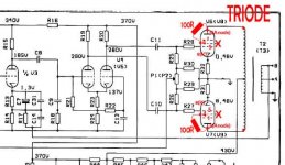
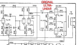
I’ve attached to this post a “before/after” schematic of the changes.
1) Disconnect the screen grid G2 (valve pin 4) from the ultralinear tap in the output transformer, by unsoldering of the R33 and R34 resistors, or even cutting the pcb traces.
2) Join, at the valve socket, the valve pins 4 (G2) and 3 (anode/plate) through a 100 ohm resistor.
Regarding this 100R resistor, I’ve read that it must be non-inductive and rated at 0.5 or 1 watt, but I’ve not read any information about what voltage rating is needed. Most resistors are rated at 200-300 volts. I’ve found the Caddock MK-132 resistors, rather expensive, but small and of radial design (this will make easier the at-the-socket mounting under the pcb), non inductive and rated at 0.75 watts and 400 volts maximum.
My doubt is if the choice of this Caddock MK-132 is correct. Are its power and 400v voltage ratings high enough for this specific use? The anode voltage in the amplifier is 430 volts and the specified voltages in different points of the circuit are indicated in the attached schematic.
Have you any suggestion on alternative resistors?
Thanks in advance
Regards
Jose
I’m planning to modify the output of my Copland CTA-501 valve amplifier from the standard ultra-linear to triode mode. I’ve searched on the net and it seems an easy modification, and fully reversible if the sound doesn’t improve. The reduction of power (from 30 to about 15 w/ch) is no problem because I use a pair of easy to drive Spendor SP1/2 loudspeakers, and my listening room is only about 11 sq. metres.
I’ve attached to this post a “before/after” schematic of the changes.
1) Disconnect the screen grid G2 (valve pin 4) from the ultralinear tap in the output transformer, by unsoldering of the R33 and R34 resistors, or even cutting the pcb traces.
2) Join, at the valve socket, the valve pins 4 (G2) and 3 (anode/plate) through a 100 ohm resistor.
Regarding this 100R resistor, I’ve read that it must be non-inductive and rated at 0.5 or 1 watt, but I’ve not read any information about what voltage rating is needed. Most resistors are rated at 200-300 volts. I’ve found the Caddock MK-132 resistors, rather expensive, but small and of radial design (this will make easier the at-the-socket mounting under the pcb), non inductive and rated at 0.75 watts and 400 volts maximum.
My doubt is if the choice of this Caddock MK-132 is correct. Are its power and 400v voltage ratings high enough for this specific use? The anode voltage in the amplifier is 430 volts and the specified voltages in different points of the circuit are indicated in the attached schematic.
Have you any suggestion on alternative resistors?
Thanks in advance
Regards
Jose
Attachments
U/L to triode cxonversion
Hi Jose
1/2 to 1 watt will be more than adequate and ideally standard carbon type but in reality any resistor will do as all it is doing is connecting the screen grid g2 to the anode. Do not get paranoid about boutique components here it is not worth it The object of the resistor is to stop parasitic oscillations in the valve and to protect the HT line/rectifier if the valve goes screen grid to control grid short
As far as voltage rating is concerned I think you have the wrong idea here. Manufacturers voltage ratings are the maximum voltage a resistor can stand across it end to end NOT where it is in the circuit. As this resistor is 100R its end to end voltage will be negligible in the position chosen.
Regards
John Caswell
The voltage rating is also related to the ability of the outer coating to break down. You can abuse this rating a bit if the resistor is mounted in free air and there are no other components near it, AND there is no possibility of human contact!
I have learned the hard way that this is not true. I was using 100 ohm 1/2 watt metal film resistors from DigiKey. I had two resistors fail. Both died the same way. The sound instantly became weak and distorted in one channel, and the resistor was obviously fried. Both failed early (a few hours) in a new amp that was not abused (HiFi listening well below max power). B+ is high though, nearly 500 volts. The resistors are PC board mounted (spaced 1/2 inch above the board) with no other components nearby.
After the second failure, I switched to two watt metal film resistors from DigiKey and Mouser. I have built 5 amplifiers since then. They have all been through my standard abuse testing including an hour or so being fed with a guitar preamp operating in heavy clipping. No more blown resistors.
1/2 to 1 watt will be more than adequate and ideally standard carbon type but in reality any resistor will do
I have learned the hard way that this is not true. I was using 100 ohm 1/2 watt metal film resistors from DigiKey. I had two resistors fail. Both died the same way. The sound instantly became weak and distorted in one channel, and the resistor was obviously fried. Both failed early (a few hours) in a new amp that was not abused (HiFi listening well below max power). B+ is high though, nearly 500 volts. The resistors are PC board mounted (spaced 1/2 inch above the board) with no other components nearby.
After the second failure, I switched to two watt metal film resistors from DigiKey and Mouser. I have built 5 amplifiers since then. They have all been through my standard abuse testing including an hour or so being fed with a guitar preamp operating in heavy clipping. No more blown resistors.
A more complex variation on the theme .... it separatly sets the DC & AC operating points.
This is one of many ways to do the same thing.
http://www.t-linespeakers.org/tubes/triode-trick.html
dave
This is one of many ways to do the same thing.
http://www.t-linespeakers.org/tubes/triode-trick.html
dave
Hi
Thank you for your answers.
SY, I know that when triode mod is done, what I'll have will be a "new" EL34, with a behaviour different to what the designer had in mind and different operational parameters. Also, I have no access to measuring equipmente other than my DMM to fine adjust anything. However, as it is a well-known and safe mod and it is fully reversible,I'd like to try it and let my ears decide.
Just for playing safe (thanks, "tubelab.com"), I probably use the Mills MRA-5 resistors non-inductive wirewound (1%, 20ppm, 5W, about $2 each). They are 200v max, but, according to John Caswell, "as this resistor is 100R its end to end voltage will be negligible in the position chosen".
Thanks to all of you
Regards
Jose
- Status
- This old topic is closed. If you want to reopen this topic, contact a moderator using the "Report Post" button.
- Home
- Amplifiers
- Tubes / Valves
- Resistors for ultralinear-to-triode conversion