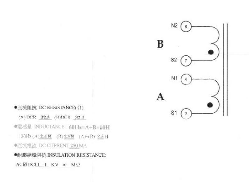
As far as I can see S and N just identify the winding sense. You need to know this when connecting the windings together, either in parallel or series. Apart from that they have no significance. For 2.5H connect N1 to N2, S1 to S2. For 10H connect N1 to S2, or N2 to S1.
If you try to use the two windings in separate parts of a circuit (even closely related parts such as successive L's in a CLCLC filter) this will not work because they are strongly coupled - you won't have two separate chokes but one transformer.
If you try to use the two windings in separate parts of a circuit (even closely related parts such as successive L's in a CLCLC filter) this will not work because they are strongly coupled - you won't have two separate chokes but one transformer.
If you try to use the two windings in separate parts of a circuit (even closely related parts such as successive L's in a CLCLC filter) this will not work because they are strongly coupled - you won't have two separate chokes but one transformer.
Right. But one might use them as a common-mode choke in both conductors (0V and B+) of the PSU...
Greetings,
Andreas
Why would you want a 2.5H common-mode choke? It would probably have far too much parasitic capacitance to block HF noise.
Lundahl recommends wiring their dual coil chokes for "improved common mode rejection" by placing one coil in the + and one in the - of the circuit. See link:
http://www.lundahl.se/pdfs/datash/1638.pdf
Lundahl recommends wiring their dual coil chokes for "improved common mode rejection" by placing one coil in the + and one in the - of the circuit.
Hi DF96,
that's what I had in mind... Must have read it when I was on the Lundahl website looking for my OPT's.
"Common-mode choke" was a bit wrong, as this usually stands for RF suppression chokes as you already said.
Greetings,
Andreas
By all means wire it as a common-mode choke if you need common-mode rejection of hum. This is rarely needed, especially when you bear in mind that when wired like this it loses all its differential-mode rejection. It might solve a grounding problem, although correct grounding is a better way to fix this, but it won't do any normal ripple smoothing.
Common-mode chokes seem to have a following, but I am going to stick my neck out here and say that I suspect it is mainly just a fashion among people who would not recognise a choke balun if one dropped on their foot! The proper place for a common-mode choke is in the mains filter before the power transformer, but then we are talking mH or 100's of uH to filter out RF.
Common-mode chokes seem to have a following, but I am going to stick my neck out here and say that I suspect it is mainly just a fashion among people who would not recognise a choke balun if one dropped on their foot! The proper place for a common-mode choke is in the mains filter before the power transformer, but then we are talking mH or 100's of uH to filter out RF.
The 'lundahl connection' places the coils in series in an adding fashion to reduce ripple. The nature of the wind has appreciable leakage inductance between the coils and it is this leakage inductance that appears as two discrete chokes in series with each coil which increases common mode noise rejection. I do not think lundahl ever calls (or intends )it a common mode connection but notes that it gives 'improved common mode suppression'.
dave
dave
dave
dave
OK, I didn't look sufficiently closely at the wiring in that Lundahl data sheet. You are right - it is not a common-mode choke but a differential-mode choke. The leakage inductance will attenuate common-mode noise. There is a possible snag: this connection may increase the common-mode noise which needs to be attenuated because the 'earthy' end of rectifier/reservoir cap is no longer grounded but now has half the ripple voltage across it. A typical can type capacitor will therefore need to be isolated from ground (OK - normal) but will still have capacitance to ground so may inject the HF components of the ripple into the chassis. This might not be a good thing! The choke might be solving a problem which the choke has created.
- Status
- This old topic is closed. If you want to reopen this topic, contact a moderator using the "Report Post" button.
- Home
- Amplifiers
- Tubes / Valves
- How to wire inductor - s and n