Rogers Cadet III to SY Red Light Diistrict or Gingertubes's Baby Huey
Hi all,
I've fixed up a Cadet amp with new Electro & polyprop caps - it sounds very good although still some hum & hiss at higher volumes.
I am looking to use the existing chassis, Tubes & iron to build something better sounding & keeping the costs to a minimum.
I thought I would go with the Gingertubes' baby huey although using the existing Cadet OPT I won't have Ultra Linear taps.
Then I came accross Sy's Red Light District amp last night.
My question to the group is: how easy would it be for a noob to change the operating points of the RLD to use ECL86 tubes (original Mullards - not matched from the Cadet). Sy references the ECL86 tube in the article he wrote as not being optimal - I wonder how sub-optimal this tube is?
How easy/difficult is it to source the correct Leds in Ireland/UK? - maybe Shoog can answer this as he seems to have experimented.
How does Led CCS compare to LM317 CCS?
Is regulating the grid voltage worthwhile on ECL86 pentodes?
I may try implementing these tricks on the existing Cadet amp although the amp PS & grounding is mediocre & difficult to modify.
All help greatly appreciated - noob's work in progress here
John
The LEDs are not a CCS, in fact the opposite- they're a constant voltage source.
In any case, it looks like you could adapt the RLD circuit to the ECL86 by reducing the LED string voltage. Instead of a string of 7 in series to give -11 to -12V, you'd use 6 in series to give you about -10V. You'd still parallel the series strings to take the current.
That said, I've built five RLDs so far, but haven't used anything except EL84. So that alone might discourage a noob- it's doable, but it's terra incognito.
The main advantage of this sort of constant voltage bias is overload performance and recovery. The amp will sound like it plays louder and more dynamic than it otherwise would.
The CCS is useful if your phase splitter is falling down on the job, but really, it's so easy to design a good phase splitter that there's very little (if any) practical advantage to running a CCS for output stage biasing.
As far as LEDs, get the cheapest, oldest ones you can find. Seriously. The best I've used so far were US$40 per thousand at a surplus shop.
I am looking to use the existing chassis, Tubes & iron to build something better sounding & keeping the costs to a minimum.
I don't know how much "wiggle room", if any, is available. Is there a reserve of current in the PSU? I'm guessing that a reserve is not available. If the amp used 6BM8s instead of 6GW8s, I'd say try an "El Cheapo" variant. The triode in the 6BM8 is very similar to those in the 12AT7, while the triode in the 6GW8 is very similar to those in the 12AX7. High gm triodes make better differential phase splitters. The 'T7 is high gm/low Rp, while the 'X7 is low gm/high Rp.
If you can tolerate the 50% reduction in O/P power, triode wiring the pentodes may be the "best" route to improved sound. Simply connect the screen grids to the plates via 100 Ohm resistors.
Thanks Sy, Eli,
Sy, I understand - here is the schematic of the Cadet - It is remarkably close to your RLD schematic to my Noob eyes although I probably don't appreciate the details. I think there is one mistake in the schematic - 6p8 cap connects between cathode of bottom output tube directly to plate of top output tube (both halves of one tube so from pin 6 to pin 8) . Anyway, I wonder if this rates as a reasonable phase spliiter? If so I will drop the CCS idea & go with LED CVS.
Eli, I think the ECL86 tubes are a 12AX7 triode & EL84 pentode equivalents so "el cheapo" not suitable? Also PS trafo I assume is built to a budget & would be just adequate to run the Cadet
John
Attachments
The input stage and phase splitter in my amp are indeed very similar to the Cadet. The direct coupling and lack of cathode bypass in the RLD were also common features on other amplifiers from the '50s and '60s.
The downside to direct coupling compared with the RC coupled and self-biasing split-load used in the Cadet is the need for a higher B+, which may not be available to you. The upsides of that approach include one less low frequency rolloff, lower parts count, the feedback returned directly rather than through an electrolytic cap, and one less possible spot for blocking.
The downside to direct coupling compared with the RC coupled and self-biasing split-load used in the Cadet is the need for a higher B+, which may not be available to you. The upsides of that approach include one less low frequency rolloff, lower parts count, the feedback returned directly rather than through an electrolytic cap, and one less possible spot for blocking.
Thanks Sy,
No higher B+ is not a possibility, at the moment anyway.
So I will try LED biasing & regulated B+ on ouput tubes, if I can. Cleaning up the ground plane (in the power amp section, anyway) & possibly changing the PS to full wave rectification was something I had considered.
Now to find 100 LEDs!
John
jkeny said:I think there is one mistake in the schematic - 6p8 cap connects between cathode of bottom output tube directly to plate of top output tube (both halves of one tube so from pin 6 to pin 8).
No, the drawing is correct. That capacitor is there on the real thing.
kopite said:Hi Stuart,
Any chance of giving me a look inside and out of your RLD amp. Just to give me an idea of layout.
Thanks.
I'll take some pix of the prototype's bottom and try to get it posted tomorrow. Layout is very straightforward.
Sorry for all the questions but would a 12V SLA battery do instead?
12V is a bit high; for EL84, you want 11.5 or so, for ECL86, it sould be a shade under 10V. I've never tried a battery there, but I don't see any reason why it wouldn't work. Doesn't look as cool....
As long as the bias is there when everything starts warming, you're fine.
kopite:
The top view of my first proto can be found here:
http://www.diyaudio.com/forums/showthread.php?postid=840474#post840474
Bottom view attached. At the top is the input connection. The ground is terminated there (it's the thick black wire that runs to the perfboard). Perf board in the middle contains the raw supplies, the one on the right has the screen regs. Shiny job on the bottom is the power entry module. The loopy black wires on the sides are shielded cables carrying the feedback signal.
The basic layout works well (dead quiet and stable), but someone with construction skills exceeding those of a spastic chimp can make a much better looking version. I've got some prettier ones which I'll photograph later this week before packing them up and shipping them to a friend of mine.
Attachments
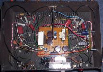
The proto was built in a discarded ST-70 cage. The "nicer" ones are done in a more typical metal-plate-on-wood-frame style, about 13"x15". Plenty of room.
The power transformer on top runs the output stage plates, heaters, and screens; the transformer for the driver stage is tucked under the power entry module.
The power transformer on top runs the output stage plates, heaters, and screens; the transformer for the driver stage is tucked under the power entry module.
- Status
- This old topic is closed. If you want to reopen this topic, contact a moderator using the "Report Post" button.
- Home
- Amplifiers
- Tubes / Valves
- Rogers Cadet III to SY's Red Light District or Gingertubes's Baby Huey