my interest in such stages was suddently perked after browzing through another thread which someone mensioned about mosfet buffers.
i am hoping to use this buffer to push power tubes over the edge, to class A2. i must say i am not extremely well versed in electronics and i may need alittle help from you guys to tidy my design.
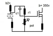
i intend to use something like a irf820 or 830. bias it up to maybe 5ma by tweaking the source resistor.
the thing that interests me most is the front of the mosfet. i was thinking of using the pot to bias the power tube connected to the source of the mosfet.
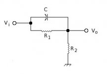
as you can see, the tube with a 'high' output impedance drives the gate via a voltage divider bypassed with a capacitor. the voltage divider lowers the DC voltage, enough to bias the tube, this way i dont need another circuit to bias the tube and the mosfet, it also takes away the need for a coupling capacitor of some sort to connect the source to the power tube.
the capacitor bypass R1 so the AC signal doesnt get divided. that way, gain isnt affected greatly. i did some workings and i realised a 500k pot and a R1 with a value of around 200k would work fine with a bypass capacitor of only 0.22uf. the 2 resistors values can be further optimized to get the right voltage at the source to bias the power tube.
does this circuit make any sense?
thanks man!
i am hoping to use this buffer to push power tubes over the edge, to class A2. i must say i am not extremely well versed in electronics and i may need alittle help from you guys to tidy my design.
i intend to use something like a irf820 or 830. bias it up to maybe 5ma by tweaking the source resistor.
the thing that interests me most is the front of the mosfet. i was thinking of using the pot to bias the power tube connected to the source of the mosfet.
as you can see, the tube with a 'high' output impedance drives the gate via a voltage divider bypassed with a capacitor. the voltage divider lowers the DC voltage, enough to bias the tube, this way i dont need another circuit to bias the tube and the mosfet, it also takes away the need for a coupling capacitor of some sort to connect the source to the power tube.
the capacitor bypass R1 so the AC signal doesnt get divided. that way, gain isnt affected greatly. i did some workings and i realised a 500k pot and a R1 with a value of around 200k would work fine with a bypass capacitor of only 0.22uf. the 2 resistors values can be further optimized to get the right voltage at the source to bias the power tube.
does this circuit make any sense?
thanks man!
Attachments
hacknet said:does this circuit make any sense?
thanks man!
One big problem. That RC coupling circuit has a zero at: 1/CR1, which doesn't present much of a problem. However, it also has a pole at: [1/C][R1 || R2]^-1, and this does cause problems since it will change when you alter the setting of the potentiometer. The lower you set that, the higher that turn-over frequency will go. You could potentially be looking at a considerable loss of low frequencies, and that will make for poor bass performance. It's best not to get too fancy here, and just couple to the MOSFET conventionally. That will also make what the MOSFET is doing independent of what the VT is doing there.
Attachments
Hello,
you could get inspiration from the various threads about TubeLab's PowerDrive, try to search the forum.
I do similar things, maybe you can get inspiration also from these:
http://giaime.altervista.org/hivolt_eng.html
you could get inspiration from the various threads about TubeLab's PowerDrive, try to search the forum.
I do similar things, maybe you can get inspiration also from these:
http://giaime.altervista.org/hivolt_eng.html
i noticed another problem with my design. tubes need a negative bias on the grids, i have positive bias. i noticed the problem after studying giaime's schematics.
i probably would need a -ve voltage rail to do any biasing with that mechanism.
miles:
i see your point man, but the way i see it, a larger capacitor and tweaking the resistor values to keep the loading low will preserve much of the signal. do you see it the way i see it?
i probably would need a -ve voltage rail to do any biasing with that mechanism.
miles:
i see your point man, but the way i see it, a larger capacitor and tweaking the resistor values to keep the loading low will preserve much of the signal. do you see it the way i see it?
- Status
- This old topic is closed. If you want to reopen this topic, contact a moderator using the "Report Post" button.