I'll be using Lundahl 1638 chokes. Consulting with Kevin (US Lundal distributor), I should be ok with the voltages and the currents they'll be used with. No value will be exceeded.
http://www.lundahl.se/pdfs/datash/1638.pdf
JD
http://www.lundahl.se/pdfs/datash/1638.pdf
JD
Jeffery, Whose chokes are you using for the HV power supply. So far I've found nothing commercially available at these voltages. I'm hoping NOT to have to special order any. Thanks Ron p
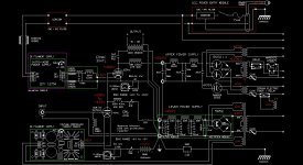
Methinks it's just about there. Added a delay and slow start circuit to the megabeast. Turn on sequence for upper supply:
1. turn on main power switch... Amperite 75 second delay to primary while 866a MV rectifier filaments heat.
2. Amperite trigers and secondary 6.3v sets the 25 second solid state 555 based timer (Sophia Electric). **In case of a power blip, the Solid State device will reset and give some time for the heaters to warm, as the Amperite will probably be too hot to give the 75 second delay**.
3. Sophia trigers and separate 6.3vct tranny heats the 6CG3 damper diode.
4. damper diode slowly heats then ground circuit in upper supply is made and full B+ is availible.
Note 1 .... The center tap of the damper diode filament transformer is biased to the cathode as to keep their potential at the same level. The Damper diode has a max rating of 900volts Cathode to heater w.r.t heater being negative (relative to cathode).
Note 2 ...I liberally use CL80's for turn on current surge for the big tranny as it's a toroid and to add just a bit of ramp up time. Redundant, maybe, but cheap and they only cost a couple of volts, not to much to worry about. The Damper Diode also costs about 20 volts or so.
The lower supply uses a 5852 Bendix, a Aerospace version of a 6X5GT. It has a 45 second heat up time, so it can be used as-is for the 20B.
JD
Attachments
Last edited:
304TL circuit
hi Frank,
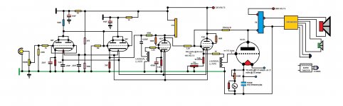
I am on the point of starting to build my 304TL SE amp. as all the other guys have said it is a mammoth task and is a different world than building with something like an EL34...but heck the enjoyment and sense of achievement when its up and running is a real blast. Anyway attached is my circuit diagram which I hope helps you out. Note the 13E1 can be replaced with 6C33...good luck and let us know how you get on...James
hi Frank,
I am on the point of starting to build my 304TL SE amp. as all the other guys have said it is a mammoth task and is a different world than building with something like an EL34...but heck the enjoyment and sense of achievement when its up and running is a real blast. Anyway attached is my circuit diagram which I hope helps you out. Note the 13E1 can be replaced with 6C33...good luck and let us know how you get on...James
I am new to the forum but I have been reading about the 833A based SE amps. I have a supply of 304TL tubes. Would this tube be suitable for a class A SE? Any suggestions for a circuit? Would the driver and output transformer selection be similar to the 833A?
Thanks in advance.
Frank
Last edited:
304TL Circuit
hi Frank,
I am on the point of starting to build my 304TL SE amp. as all the other guys have said it is a mammoth task and is a different world than building with something like an EL34...but heck the enjoyment and sense of achievement when its up and running is a real blast. Anyway attached is my circuit diagram which I hope helps you out. Note the 13E1 can be replaced with 6C33...good luck and let us know how you get on...James
Attachments
304 amp
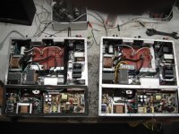
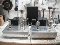
Well, I've built a pair of them based on a fellow's design called "bitches brew", you can search that on the web. It's a battery biased (on the el 20a ) driver, direct coupled parafeed design and does work well. Electroprint made the coupling choke and the output transformers, Lundahl input. Standard transformers for high voltage (1.5kv) and Russian oil caps for the hv power supply. Since I was worried about size and weight (97lbs!) I'm not using tubes for power supplies, I'm infact using a switching power supply for the 304 heaters, a 50 amp one, a 20a wouldn't handle the inrush current. And in addition I'm staging the two halves of the 304 heaters AND the two amps to start slowly. In the chassis is a cooling fan which exits at the base of the 304s within a glass chimney, you CAN heat the room with these. And if you are worried about noise with a switching supply; they cycle at 50kz, a bit above what I can hear with a resonance at 25 which a choke dampens. You DON'T breadboard these you Plywood them. good luck rp
Well, I've built a pair of them based on a fellow's design called "bitches brew", you can search that on the web. It's a battery biased (on the el 20a ) driver, direct coupled parafeed design and does work well. Electroprint made the coupling choke and the output transformers, Lundahl input. Standard transformers for high voltage (1.5kv) and Russian oil caps for the hv power supply. Since I was worried about size and weight (97lbs!) I'm not using tubes for power supplies, I'm infact using a switching power supply for the 304 heaters, a 50 amp one, a 20a wouldn't handle the inrush current. And in addition I'm staging the two halves of the 304 heaters AND the two amps to start slowly. In the chassis is a cooling fan which exits at the base of the 304s within a glass chimney, you CAN heat the room with these. And if you are worried about noise with a switching supply; they cycle at 50kz, a bit above what I can hear with a resonance at 25 which a choke dampens. You DON'T breadboard these you Plywood them. good luck rp
Attachments
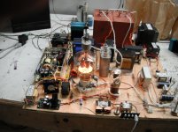
Dissipation in BTU's; a lot, but tubes are running just under 1.5kv 1480v if I recall and indeed 100ma rp
1480v @ 100ma = less than 150 watts dissipation.
This is low for a 304TL.
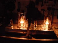
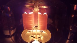
The reason I asked is that in your pictures, the plates of your 304TLs don't look like they are brightly glowing red. These tubes need to have glowing plates to function properly. Have you tried to up the dissipation to around 250 watts? Like 1480 volts @ 150-175ma? The tube will be happier at this operating point. I wouldn't run 304TLs with less than 225 watts dissipation.
The cathodes of the 304TL are good up to 900ma of current. The reason these tubes make good class "A" amplifiers is that they can handle A LOT of current.
They ARE brighter than the pix show, I'm not running them harder because they are doing fine job running my huge OLD ESS amt6's and heat AND price of the tubes make me be a little conservative. The 100ma is what I remember from setting them up, it MIGHT be a little higher, but not much. I would have to track down my records, this was a few years ago, and I'm getting OLD! rp
OK, great.
I never knew this, but these tubes have tantalum plates. The plates act as the "getter" by absorbing gas, but they have to be glowing cherry red in order for them to do this properly. That's why these tubes have no silver spot inside the glass envelope; the red hot plates absorb the gas.
304TLs were used a lot during WWII in radar and many that are put into service now don't survive at first turn on because they have become "gassy". A LOT of people have ruined these tubes because they don't follow some easy steps to get these tubes in working condition. There is a way around this, I think there was a post on this forum years ago on how somebody found a burn-in method to get these tubes within spec again after so many years of not being used.
I think it went like this:
1) power up filament for some specified amount of time.
2) ground the grid
3) apply plate voltage through a variac starting with 50-100 volts on the plate.
Basically, since the grid is at ground potential the tube is going to pull A LOT of current so you want to start off with a low plate voltage so as not to exceed tube ratings. As the tube heats up and the plates turn red, the plates start to eat up the stray gas in the tube.
This is a really short condensed version of what needs to be done. If I can find the info I will post it.
Maybe somebody knows what I am talking about and can direct to where the information is located?
Thanks, Daniel
EDIT: Here's something I found on Ebay:
Testing Methods for 304TL
Before testing all terminals were cleaned. Tubes were then burned in at 300W (maximum plate dissipation, red plate) using progressively higher plate voltages until bias current and grid current stabilized for one hour. This eliminates excess gas from these tubes sitting on a shelf for 60 years.
Both tubes show negligible gas current, plate current is stable, and test settings are repeatable from a cold start.
Last edited:
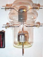
Huh didn't know any of that, one of the tubes was in an original box dated 1944! I just warmed them up slowly and did use a variac to see what they did. In the pic that Satelitis posted his tube has a flanged metal nicely aglow, the ones I'm using have no flange and are coated with a gray material, getter stuff? rp
The gray material is Zirconium IIRC, which does also act as a getter. I don't know if there is tantalum underneath or not.
The attached picture shows tantalum (shiny) on the "domed" part of the plate and zirconium (dull gray) on the sides.
This is another Eimac tube, a VT127.
The attached picture shows tantalum (shiny) on the "domed" part of the plate and zirconium (dull gray) on the sides.
This is another Eimac tube, a VT127.
Attachments
- Home
- Amplifiers
- Tubes / Valves
- 304TL based Class A