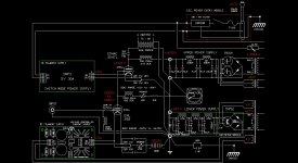
latest developmental schematic..barring any more changes, about all that's left to do is calculate the values for capacitors for the cathode bias balancing resistors and trim pot bypass for the EML20B driver.... and once the iron arrives, recalc the values using real DCR measurements and inductance values supplied form their maufacturers... oh and scheme up delays for the 866a's
JD
JD
Attachments
Last edited:
The heater requirements for the 304TL are quite "rigorous" 5 volts but at 25 amps... yep twenty five. In a single end configuration, AC , even with all the "bells and whistles"..ie, hum pot, twisted pair leads etc.. will have a fair ammount of hum. DC is much better, but a normal DC supply (as used for the lower tube) can not be built to regulate all that current. Also finding chokes at 25A is fairly difficult in appropriate (non-microwave) frequencies / Henries, that aren't the size of a small automobile.
Each tube has to have it's own heater supply, they can not be shared as this is a two stage using DHT, where the cathode is also the heater/filament.
AC is said to sound good as a heater voltage supply( but can have a hum problem if not properly implemented), and series regulated DC less so, DC shunt regulation supposedly sounds better than series, and a Voltage controlled Current supply supposedly is the best DC heater supply sound wise. This can supply enough current for the demands of the 20B, but such a design can't be built for the 25A needed for the 304TL.... I really wish it could, but alas.......have to make due with what is possible.
JD
I have been using 4mH/13A chokes for my 304TL amp and they were the size of a typical 10H/100mA choke. It was a CLC filter. I switched to LC for other projects with "smaller" tubes (after the 304TL you list GM70's and others among the small tubes).
Hum with AC heating can probably be nulled somehow but the intermodulation distortion due to the 50/60Hz cannot be cancelled an you will get 1050 and 950 Hz etc... out of a 1kHz tone. DC heating fixes the problem (as long as it is well implemented).
Have fun
Gianluca
I was wondering about filiment warm up on the 304s. Seems like 25a is QUITE a jolt, I'm wondering about running the filiments in series on startup and switching (after a bit, 30sec??) to parallel for running via relay. Yes also running on DC and of course delaying HV till after filiment cycle. Thoughts? Ron p
I was wondering about filiment warm up on the 304s. Seems like 25a is QUITE a jolt, I'm wondering about running the filiments in series on startup and switching (after a bit, 30sec??) to parallel for running via relay. Yes also running on DC and of course delaying HV till after filiment cycle. Thoughts? Ron p
All you need is a resistor (maybe an ohm or two) in series with the filament and a relay to short it after 5 seconds. If the filament draws 25a while hot then its probably close to 100a during initial surge.
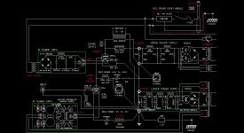
Almost there....to not have to worry about finding a 36lb $250 choke (1 for each channel) Decided to drop the SMPS idea and an AC scheme for the 304TL heater...
Also, Jac at Jac Music (EML) corrected his data page on the 20B, this lead me to change the bias desgn a bit for the tube.
Here's the state of the schematic.....
JD
Also, Jac at Jac Music (EML) corrected his data page on the 20B, this lead me to change the bias desgn a bit for the tube.
Here's the state of the schematic.....
JD
Attachments
I had thought that in series (with dc that is) since there are two filiments the positive side would be, err, more positive than the negative in relation to the plates and grids, thus having more or less half the tube doing more or less work. Since these tubes seem to be just four tubes stuffed together, maybe better output? Or am I just full of it , again? ron p
Hmm, maybe I'm full of it you mean?, you sound like my wife, sigh. And I've got ANOTHER filiment type question; On Jeff's latest schematic he is feeding 10v to the series filiments, and the negative plate return is going through a pair of 10 ohm resistors, one on each side of the filiments. Since they are in series why not just return to the centre tap and do away with the resistors?
aarrrggghhhh....
forgot to take into account the voltage drop from the bridge rectifier...Looks like I'll need to go with at least an 18V transformer (about 21v unloaded)... I was reading the voltage off the wrong R in the PSUD schematic... looking at the "LOAD" R now, was looking at the voltage across the R in the final RC....I need to get some glasses in my old age...
Jeff
Last edited:
Jeff
are you sure you need 2000uF before the 10mH choke on the 340TL fils? If gapped properly (15A) it should be fine as input choke. And what is that 60R resistor on the filaments supply??? You do need more secondary and primary taps at the power transformer to get exactly 10V at the filament ... it is a trial and error process. I usually rewire my multiple secondaries transformer 4 or 5 times to get exactly the voltage I need after the bridge and filter.
I believe the anmeters will not work wired that way. Probably you will not need that 50R trimpot on the 20B cathode: you can bias the tube at 7.2V, (7.2-2.5)V or (7.2+2.5)V which should give plenty of room for adjustments in conjunction with the 1kR pot in the anode circuit.
Ron,
what CT??
Gianluca..... I was trying to dial in the 10V using PSUD, but in my last post I said I made a mistake in reading the voltage off the wrong resistor. I was reading the voltage off the 62R instead of the load resistor which was .8R (filament resistance of the 304TL in series). So all that "stuff" you're mentioning is gone in my next schematic update.
I'm trying to use easy to find transformers that are "off the shelf" if possible.
Custom iron is not a solution when there are less costly and more timely alternatives. I've already spent a huge chunk of change for the custom plate chokes (Electra-Print and Magnequest) and a very tidy sum for the custom output transformer (Tribute).
The ammeters have worked that way in another amp I have built, but just a little differently. For reading the 304TL current the ammeter takes place of measuring current across a 1 ohm resistor with a Fluke V.O,M, (which is how my 300B amp works with the two test points). The ammeter requires no resistor and I'm using the same test points.
The ammeter for the 20B just measures the current through that tube across the tube to ground
The pot after the 7.2v battery adjusts the bias in the 20B (which gives me a voltage range of -6 to -8 taking into account the offset from biasing at the + of the filament supply), but one pot effects both tubes since they share the stacked supply... If I change the bias on the 304, the 20B will also change. I want to get 43ma on the 20B if possible regardless of range of the plate voltage the bias pot for the 304 allows, while trying to maintain the 125ma on the 304. If I change the bias on the 20b, the 304 will change. Having both let's me find the best relationship to get "both" biases as close to design values as possible. Adjustments will be back and fourth a bit to find the values, also having both lets me adjust for tube aging as well.
Jeff
Jeff
are you sure you need 2000uF before the 10mH choke on the 340TL fils? If gapped properly (15A) it should be fine as input choke. And what is that 60R resistor on the filaments supply??? You do need more secondary and primary taps at the power transformer to get exactly 10V at the filament ... it is a trial and error process. I usually rewire my multiple secondaries transformer 4 or 5 times to get exactly the voltage I need after the bridge and filter.
I believe the anmeters will not work wired that way. Probably you will not need that 50R trimpot on the 20B cathode: you can bias the tube at 7.2V, (7.2-2.5)V or (7.2+2.5)V which should give plenty of room for adjustments in conjunction with the 1kR pot in the anode circuit.
Ron,
what CT??
Last edited:
OK. One option you have (PSUD will not give you a 100% accuracy result ... you know that) is to use dropping resistors but they are a pain: you will add heat to heat, thats why I ended with a multitapped transformer for the filaments (which I use for many other tubes as well).
I had a pot in the lower tube cathode at the very beginning and I can say you can most probably do without in the final amp. You can rewire the 20B fil supply to fix the bias of the tube at 7.3V +/- 2.5V, that should give enough room to bias both the tubes and you are saving more parts.
The 1kR trimpot is what you really need to dial the 304 ... you will see ;-)
Just fix the 20B bias and fine tune the 304TL
The ct I was refering to is just the connection between the two filiments when in series. As I am looking at the schematic with the TEN v supply to the 304 filiments; they are only shown as a single filiment, but they are in series and the connection just is not shown. So there is a 20 ohm loop from + to - which is connected to the plate - supply, why can't that wire just go to the filiment interconnection. Am I just being dense, AGAIN? Ronp
Ron, in my schematic I was using a common stratagy for DHT's to 'equalize" the bias voltage across the filaments at the tube to keep the "loop" small.
This would also allow for a filament transformer that did not have a center tap to use as the bias voltage input. With the two resistors as shown in my schematic, the bias supply in would go where in an AC heater setup a hum pot would otherwise go, and in an AC heater setup, the center tap of the hum pot would go to the bias supply.
JD
The ct I was refering to is just the connection between the two filiments when in series. As I am looking at the schematic with the TEN v supply to the 304 filiments; they are only shown as a single filiment, but they are in series and the connection just is not shown. So there is a 20 ohm loop from + to - which is connected to the plate - supply, why can't that wire just go to the filiment interconnection. Am I just being dense, AGAIN? Ronp
ok..... tidy'd up the DC heater supply for the 304. Found and appropriate transformer to give enough voltage to compansate for the voltage drops of the bridge and the choke to get the +10. Also the transformer has a center tap which I'll use to bias the 304 and get rid of the resistors that were previously at the cathode...
Jeff
Jeff
Attachments
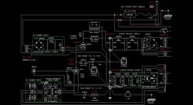
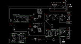
more tweeking the filament supply... added bleeders and added another LC.
I got very lucky and found these chokes for 6 dollars each. They retail around $60 each, so at the surplus price, all the really do is add weight to the amp rather than cost. Now I understand the term "boat anchor". Also found a good deal on the 20000uf 25v caps as well.
JD
I got very lucky and found these chokes for 6 dollars each. They retail around $60 each, so at the surplus price, all the really do is add weight to the amp rather than cost. Now I understand the term "boat anchor". Also found a good deal on the 20000uf 25v caps as well.
JD
Attachments
So who's got the HOT deals, if you don't mind. and I've got a question regarding the 200ma ammeter. Howzat work, looks like it goes from - upper power supply to upper power supply - wire, reading current flow in wire resistance? Or are you talking inductive pickup. keep up the good work ron p
Found them on eBay, but alas I wiped the seller out.
SPC 20975 High Current Choke Inductor Type - eBay (item 150413495793 end time Feb-18-10 10:51:17 PST)
The ammeter I'm using does not need to measure across a resistor. The pickup points in the schematic are where I had test points in a similar 300BXLS amp, but I was using a VOM and had a 1 ohm resistor between the points. I may have to relocate the T.P.'s (test ponts / pickup points), but that not an issue.
JD
So who's got the HOT deals, if you don't mind. and I've got a question regarding the 200ma ammeter. Howzat work, looks like it goes from - upper power supply to upper power supply - wire, reading current flow in wire resistance? Or are you talking inductive pickup. keep up the good work ron p
- Home
- Amplifiers
- Tubes / Valves
- 304TL based Class A