Tell tail signs of good feedback useage?
What kinds of things under testing and or simulation would lead you to
believe the feedback you are implimenting is correct and or good?
If it's negative feedback would you look for reduction in gain,distortion as
good signs the feedback is doing what it's suppose to do?
Along the same lines what would key towards bad implementations of feedback?
Any suggestions as to propper exercises for the use of feedback?
Re: Tell tail signs of good feedback useage?
Stability would be important. I would feed the amp with square waves (low-passed at 100k or so, we need to stay realistic), and make sure that there is not too much ringing, especially with cap loads.
Also look at clipping behaviour, to make sure the clipping recovery is reasonable fast (say a handfull of uSecs). No sticking to the rails!
This is not really a test of the feedback itself as well as the complete amp with neg feedback. I guess that's what you are interested in.
Jan Didden
kegger said:What kinds of things under testing and or simulation would lead you to
believe the feedback you are implimenting is correct and or good?
If it's negative feedback would you look for reduction in gain,distortion as
good signs the feedback is doing what it's suppose to do?
Along the same lines what would key towards bad implementations of feedback?
Any suggestions as to propper exercises for the use of feedback?
Stability would be important. I would feed the amp with square waves (low-passed at 100k or so, we need to stay realistic), and make sure that there is not too much ringing, especially with cap loads.
Also look at clipping behaviour, to make sure the clipping recovery is reasonable fast (say a handfull of uSecs). No sticking to the rails!
This is not really a test of the feedback itself as well as the complete amp with neg feedback. I guess that's what you are interested in.
Jan Didden
HF instability is more of a problem than LF instability....One of the tricks I use is to put a piezo tweeter across a dummy resistive load with leads # 2meters length or so. Piezo's have a horrible negative impedance characteristic which many tube amps rebel at. A low level square wave between 1-5Khz will show all the ringing and overshoot. Scope probe earthing is also important.
A well designed 3-4 stage amp can have the global nfb loop increased by at least 10dB without showing signs of instability in a standard long-lead load. This (was) is the old industry standard test.
LF instability (i.e motorboating) can be caused by poor supply decoupling and overvalued interstage coupling cap(s). As with the global nfb comments, if the loop nfb is increased by 10dB and motorboating occurs, reduce the value of the interstage coupling caps by a 1/3. The bass will be somewhat fuller.
richj
Piezo's have a horrible negative impedance characteristic which many tube amps rebel at.
I suspect you meant negative phase angle of impedance, as in capacitive. I doubt that piezo speakers have a negative magnitude of impedance. Using a piezo as part of a test load seems like a good idea, though.
kegger said:I'm interested in all forms of NFB, but at the moment experimenting with local NFB.
Do you mean cathode followers?
How are your experiments going?
Basically my experiments have been plate to grid feedback around single stages.
Douglas here, AKA Bandersnatch clued me into an interesting way to do it on the
Schmidt/LTP type phase splitter stage which worked for what I wanted very well.
Now I'm working on first gain stages trying the same thing and like what I see quite
a bit, now I just need to get it into the real world and see how it actually performs.
(it's all on spice simulation at the moment for this stage)
My main intent was to be able to do away with (global/loop/from the output trannie)
back to the front of the amp while keeping the sensitivity of the amp low enough to
still be able to use active linestages while in the process hopefully making the amp
perform and sound better, so far so good! More along the lines of modifying things
then actually builds from scratch. But as things tend to go if I get what I want they
will lead to implimentations into my own creations, which some have.
I'm not trying to say that global/loop is something that is to be definatly avoided but
at the moment experimenting without it and believe I like the results without using it.
kegger said:Basically my experiments have been plate to grid feedback around single stages.
I'm not trying to say that global/loop is something that is to be definatly avoided but
at the moment experimenting without it and believe I like the results without using it.
I've also tried 1st stage plate to grid with direct resistor and pulling the grid g1 with a negative bias the opposite way if you see this. This will lower the input Z and due to DC shift will place a cap on the input. In a way this imposes a grid bias condition and away from autobias.
I deliberately avoided a coupling cap with resistor from plate to grid....project rethink.... the long time constant created a hangover effect but has to be optimised to avoid another LF pole in the LF response below o/p tranny cutoff. When the first stage has a small signal pentode some screen grid interaction occurs, complicating matters.
A drawback with direct coupling is that a consistent DC performance with the same tube type from different vendor cannot be acheived. This implies the AC thd harmonic performance esp with pentodes will be inconsistent and I've found this has an effect on sound quality.
Global feedback say 15-20dB is a desirable asset to correct LS deficiencies.
richj
"(I deliberately avoided a coupling cap with resistor from plate to grid....project rethink).... the long time constant created a hangover effect but has to be optimised to avoid another LF pole in the LF response below o/p tranny cutoff."
That is basically what I'm playing with as of now.
Not sure I follow if you tried it or if you just avoided it all together?
Yes I've been experimenting with the cap size to "tune" the low frequency
response, very interesting aspect of that implimentation. I need to hear it now.
It's on a triode front end (12bh7) and I'm running a 120k resistor with a .2uf cap now.
So far all seems to check out and look good at both ends of the spectrum, but I need to put it into play.
Using standard Pentode setup (max gain) is unpredictable from type to type......g2 voltage variations between same makes is the pain in the a-rse and hard to optimise.......pentode strapped as triode is way better but so is low gain (!) can't win and need step up tranny.....so input Z goes down.
The input Z for a practical circuit with plate/grid fb can introduce loading thd from previous stage if tube which can defeat purpose. parafeed /cathode follower is best. (Another transformer ??.)
As regards the LF response, I ran into transient recovery troubles when global feedback was applied. (p-p amp) On most p-p designs if one does the loop gain freq response graph with feedback applied, there becomes a point usually under 15Hz when stage gain runs out causing a slight peak in the response (around 1-3dB). Although way under normal o/p tranny cutoff, the gain has to continue low enough in the LF end to provide enough global nfb for LS damping. If youv'e followed the picture, one is looking for at least 15-20dB nfb at the LS LF driver resonance i.e 20-35Hz dep'ng on cabinet.
The Radiotron handbook 4th ed page ch. 17<complete amplifiers>p.751 re Williamson.
To put it crumbly......"our modified front end with 10dB internal feedback from plate to grid" the cap between anode/g1 must not interact with the global loop response curve otherwise the LF end with behave strangely with overhang with long time constants.
Although I did alot of work on this, the overall performance was good but another servo circuit is required to compensate for drift/time to maintain correct bias conditions. Complex !! Fair to say, the splitload phasesplitter as it stands is the simplest way of 100% nfb for that stage but I remain stuck with the inconsistency of standard pentode voltage variations for max 40dB gain.
Are you with me ??
richj
I believe I'm with yu so far.
And from paraphrasing what yu wrote one aspect seems to be global
NFB gets tricky with some of those situations when also using local?
So I shouldn't see "some" of those issues with just using local NFB.
My intent was just using enough feedback to get my gain where I wanted
while at the same time hopefully improving things for sound and specs.
Still got a lot more testing and evaluating to do on my part.
Thanks for sharing!")
And from paraphrasing what yu wrote one aspect seems to be global
NFB gets tricky with some of those situations when also using local?
So I shouldn't see "some" of those issues with just using local NFB.
My intent was just using enough feedback to get my gain where I wanted
while at the same time hopefully improving things for sound and specs.
Still got a lot more testing and evaluating to do on my part.
Thanks for sharing!
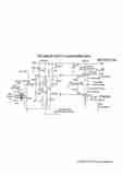
Here is circuit I played with......one could use another pentode. Conflicts ? The real problem is repeatability...as with tube designs i.e put another tube in and one gets different results !
Aikenamps pages may assist further.
richj
Aikenamps pages may assist further.
richj
Attachments
That is pretty funny! LOL! You picture is just a touch, just a touch small,,,, lol!
OK maybe it wasn't that funny but I just got home from cards and beers and it was pretty funny to me.
I'll post a pic of mine later after some more coherence here on my part. I'll post a big Pic!
OK maybe it wasn't that funny but I just got home from cards and beers and it was pretty funny to me.
I'll post a pic of mine later after some more coherence here on my part.
I'll post a big Pic!Aren't some amps run on the edge of stability, eg. willimason at lf's?
An original Williamson is unconditionally stable but the phase margin is very low which gives a peak in the LF response that is no very nice. The real problems start when you start to modify the original circuit for instance by using an output transformer that is not according to the original specifications, then it is easy to run into stability problems. What you can do is to introduce a phase corrective network for LF, by adding a more or less complex network you can achieve different degree of improvement. See here for a original Williamson where you see the LF peak http://www.tubetvr.com/Williamson.pdf and here the same amplifier with phase compensation http://www.tubetvr.com/Williamson_comp2.pdf
I heard about the maximum is 26dbs and around 30 ish for transistor amps?
There is no fixed limit but it is more difficult in a amplifier with output transformer, 26dB is probably close to what has been used, with phase compensation this can be extended but maybe it adds more complexity than what you get in worthwhile improvement. OTL amps like Futterman have had higher amount of feedback and there is no limit really, you can make an OTL stable for unity gain as an OPamp if you really wanted too. Transistor amps often use dominant pole compensation which give an open loop bandwidth of as low as 100 Hz but they can then easily be made stable for unity gain, (note! more complicated phase compensation networks allows wider open loop bandwidth but with the same degree of stability as dominant pole)
Regards Hans
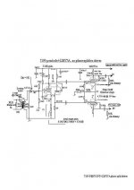
Kegger....wrong format !
The orig Mullard 20W at used 30dB glob nfb QUOTE.....had to be increased to 40dB before long lead instability was noticed.
SO a 20dB global nfb amp should accept at least 35dB before the same happens.(if well designed)
richj
The orig Mullard 20W at used 30dB glob nfb QUOTE.....had to be increased to 40dB before long lead instability was noticed.
SO a 20dB global nfb amp should accept at least 35dB before the same happens.(if well designed)
richj
Attachments
Regarding the hump in the LF response below tranny cutoff--I found this was reduced by increasing the output stage coupling caps (to g1). The trick is not to overdo it as it can lead to output stage hangover or lockup before signal recovery and in guitar amps sounds horrid. A low Z power driver stage goes a long way.
A step RC network in the global nfb path also helps.....in curtailing the HF response.
Setting up a homemade p-p amp for max attainable stability and flat response requires considerable knowledge and it's probably fair to say every designer or engineer has their own way of approaching this. I have mine and it works !! But a decent o/p tranny dores help.,
richj
- Status
- This old topic is closed. If you want to reopen this topic, contact a moderator using the "Report Post" button.
- Home
- Amplifiers
- Tubes / Valves
- Tell-tale signs of good feedback usage?