hi there guys! I'm trying to start my tube amp and I need some advices on steps I must follow in order to do the propert things. I'm not sure there is a step by step guide for beginners like me. What should I measure, what should I follow .. things like that. I'm using this schema:
http://www.arrakis.es/~igapop/6l6.htm
If I need to post more details I would do it happly.
thanks!
http://www.arrakis.es/~igapop/6l6.htm
If I need to post more details I would do it happly.
thanks!
This schematic is another version of the Williamson amplifier (including the infamous design mistake- the low frequency stability will be marginal). The design is analyzed in detail in the book "Valve Amplifiers," and there are probably 10,000 discussions of every aspect of it here and at other tube forums. That's the key word you need- Williamson.
It would be worthwhile to try to find a copy of the David Hafler article in Audio where he builds the Williamson with an Ultralinear output stage like the one in this schematic. He even discusses fixing the LF problem. A little search engine work will pay off.
It would be worthwhile to try to find a copy of the David Hafler article in Audio where he builds the Williamson with an Ultralinear output stage like the one in this schematic. He even discusses fixing the LF problem. A little search engine work will pay off.
I was reading up on that as best I could understand, and from what I gather from these discussions is that the Williamson design lacks in the pre-amp stage just before going to the final PP stage (regardless of whether it's ultralinear), is this correct? For example the 47k resistors, etc.
My question is, at what point in time were better designs/tweaks commonplace, and did this flaw mostly plague hi-fi amps while guitar amps did not care as much with the response?
On the sites I've found that have a great deal of schematics, such as these (and please suggest more cool sites like these you've run across):
http://www.triodeel.com/schindex.htm
http://tdsl.duncanamps.com/schematics.php
http://www.machmat.com/schema/index.htm
Are a lot of the older (late 50's / early 60's) amps prone to some performance problems if duplicated today without current knowledge?
And does the Willliamson flaw affect mostly the 6L6 family of designs, or is it across the board with just about any amp of similar design in that time frame?
As SY said, I would eliminate one RC network for better stability on low end.
Also, a constant bias of output tubes would be more efficient.
And I would decrease values of resistors in the global negative feedback at least ten times.
Check this one, you may like it more (I am listening currently very similar one that uses 6P3S tubes):
Also, a constant bias of output tubes would be more efficient.
And I would decrease values of resistors in the global negative feedback at least ten times.
Check this one, you may like it more (I am listening currently very similar one that uses 6P3S tubes):
Attachments
Thanks, I've checked out all the Altec Lansing designs as well, and have them saved on my hard drive.
I didn't originally post before on this thread, but
I was just curious for informational purposes as to problems with the original designs and how to "see" one that needed some adjustment.
I see that A-L did some original designs with offbeat tubes like the 811-A, etc.
I have a few projects to work on for now, but I think my very first or second post here was about a design using the 807, as they have a lot of power and in the 1625 version (different filament voltage) they are said to be in big supply (NOS military surplus), and cheap. So down the road, as I learn more I'd like to try a design based on these, since they are cool looking too with the plate cap.
I've seen a few DIY designs, but the only commercial one I see so far with a free schematic online is the Acrosound (TO-290 and TO-300 OT),
which is also a Williamson design, showing usage both with and without ultralinear. Any comments on this one would be appreciated too, as that's something I'd like to try maybe around Easter or so:
Schematic here, not sure if it's hi-fi or not.
Also the diagram shows KT-66 6L6 or 807
Does that mean that I could perhaps just take any circuit using 6L6GC's and substitute 807's or 1625's (not changing the component values) provided I rewire the socket and provide plate caps, since the 807's are rated at a much higher wattage and could breeze through it?
http://www.nijnkonijn.nl/machmat/schema/power/ppp/acro206.gif
frank754 said:The 807's I believe need a 5 pin socket and are not cheap, and the 1625's need a special 7 pin socket as well, a bit unusual but the sockets are still available for a just a few bucks too.
At least, it is much cheaper than used on German bombers (LS-50 by Telefunken).
807 was made of a mass production ray tetrode 6L6, LS-50 was specially designed ray pentode (strict alignment of grids that is expensive in manufacturing). Nikel plate of LS-50 could survire red color, but 807 was cheaper to replace.
Hi Frank,
They're actually cheaper than octal sockets if you buy the new stock ceramic Shuguang's. I had got some straight from China for evaluation and even with duty, exchange and shipping, came to about 1/3 what any retailer sells them for here.
Cheers!
frank754 said:The 807's I believe need a 5 pin socket and are not cheap...
They're actually cheaper than octal sockets if you buy the new stock ceramic Shuguang's. I had got some straight from China for evaluation and even with duty, exchange and shipping, came to about 1/3 what any retailer sells them for here.
Cheers!
sorenj07 said:unfortunately, that schematic is tiny. if you have to resize it to be able to host it on diyaudio's server, try imageshack.us, they do everything i need when i want to post pics on a forum.
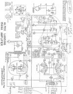
This one looks better, no graffity.
http://www.triodeel.com/al1568a.gif
problems
guys, thank you all for your replies. now I'm in this situation: the amplifier is "working", it amplifies the input but has some noise. also if I use the negative reaction the noise disappear but also the amplification disappear. more important: I can't measure the voltage on the anod of one final tube (I have a small digital multimeter that show me 1). if I plug out the second tube from the chain (6n2p) then I have the same voltage on both anods of the final tubes. somebody told me there is an oscilation of one tube and that I need an osciloscop ... unfortunatelly I don't have one. well, I hope you understand what I just described you here ... and I hope you can help me.. thanks
guys, thank you all for your replies. now I'm in this situation: the amplifier is "working", it amplifies the input but has some noise. also if I use the negative reaction the noise disappear but also the amplification disappear. more important: I can't measure the voltage on the anod of one final tube (I have a small digital multimeter that show me 1). if I plug out the second tube from the chain (6n2p) then I have the same voltage on both anods of the final tubes. somebody told me there is an oscilation of one tube and that I need an osciloscop ... unfortunatelly I don't have one. well, I hope you understand what I just described you here ... and I hope you can help me.. thanks
for sy: you mean to change the 220 nf capacitor from anod of 6n2p to 6p3s with a 40nf or less ?
for wavebourn: I saw that solution many times (to have only one RC network in the cathods of 6p3s). a constant bias means to obtain a constant voltage from the psu and to apply it to the tubes? also, how can I email you for some more issues on this schema? or you prefer to discuss them here?
thanks
for wavebourn: I saw that solution many times (to have only one RC network in the cathods of 6p3s). a constant bias means to obtain a constant voltage from the psu and to apply it to the tubes? also, how can I email you for some more issues on this schema? or you prefer to discuss them here?
thanks
vlucian said:for sy: you mean to change the 220 nf capacitor from anod of 6n2p to 6p3s with a 40nf or less ?
for wavebourn: I saw that solution many times (to have only one RC network in the cathods of 6p3s). a constant bias means to obtain a constant voltage from the psu and to apply it to the tubes? also, how can I email you for some more issues on this schema? or you prefer to discuss them here?
thanks
No, I mean capacitors between anodes and grids. SY suggested you to shift poles, I suggested to remove them. It is up to you to decide what do you prefer.
hmm
no offence but as far as I understand english, sy said to reduce that capacitor from the driver to the output stage by a factor of 5.
remove the polarized capacitors from final tubes anodes? I uderstood they must be there and only one schema has them with inversed poles. but why I can't measure one anodic voltage?
thank
- Status
- This old topic is closed. If you want to reopen this topic, contact a moderator using the "Report Post" button.
- Home
- Amplifiers
- Tubes / Valves
- starting PP - 6p3s