Could an LM317 be used effectively as a current source, to develop a fixed voltage across a resistor to apply to the gate of a MOSFET series regulator, do you think?
Yes, it could. There are a lot of CCS options; in the regs I was using in my tube amps some years back, we used a simple jFET current source to pull a reference voltage across a resistor. But whichever method is used, I'd strongly recommend temperature compensation. And the use of wirewound resistors- high voltages mean lots of excess noise.
I guess the trick is to to strap a zener across the LM317, so its maximum voltage can't be exceeded when the amp is under low signal conditions and the raw B+ is high. The LM317/zener combination would have to be in series with another resistor, I suppose, to minimize the risk of that happening.
But that, of course, means you have to pay close attention to what happens at the reg output during startup.
The more I look at this, the more I think that a bypassed Maida is still your best bet. The parts count will be about the same as your CCS reference scheme plus pass device and the performance will be better because of the feedback.
The more I look at this, the more I think that a bypassed Maida is still your best bet. The parts count will be about the same as your CCS reference scheme plus pass device and the performance will be better because of the feedback.
SY -- how about 10 or 15 mA ? -- I would compare the Maida, bypassed Maida and LastPAS regulators.
I am a bit leeeeerrrry of connecting my HP3577 to an HV power supply to run the impedance, but at least I can get an RMS estimate of the noise.
Should this be split to another thread?
I am a bit leeeeerrrry
of connecting my HP3577 to an HV power supply to run the impedance, but at least I can get an RMS estimate of the noise.Should this be split to another thread?
ray_moth said:Hi Wavebourn,
Thanks for putting up the schematic and the explanation. I must be a bit slow, I can't see a positive FB loop nor what would cause a soft start nor how it senses the amp starting to draw current. Could you please give me a clue?
The reference voltage B+ regulator takes from bias shunt regulator. Bias shunt regulator takes current from B+ regulator through the load. When no load the current is small and it very slowly charges the capacitor in the bias regulator; but if it is a refererence voltage for the B+ regulator it's increase causes increase of it's voltage that increases current that charges the cap in the bias regulator and so on... As soon as toobs become hot they start draw current and more quickly charge the cap in bias regulator up to the zener + VBE value, now full reference voltage is applied to B+ regulator and it increases the output voltage up to the nominal value.
However, if you draw a current from the bias regulator that is higher than the current that initially flows from B+ regulator, it will never start. Use it for bias purposes only.
Hi RAY MOTH ,
I am a big fan of LM 317T ( I have hundreds of them on my
stock and I use it everytime it’s possible ) .
I agree entirely with SY , that Michael Maida regulator is
the simplest and the best design of HT regulators .
But if you don’t want to use it , the decision belongs to you .
About your idea to use the LM 317T as a CCS , feeding a
resistor and strapped with a zener diode acroos it , regar-
ding to protect it against H.V. , I think that it will not work
any way , because with HIGH VOLTAGE like that , the zener
will take control , and the LM317 will lost the control about the
current , making the resistor (s) on the circuit , the only thing
to limit the circulating current . I do not recommend to do that .
If you really want to do that , make it with a semiconductorized
CCS , and in this case , the best choice would be “The Ring of
Two “ , that uses two HV transistors , and has good stability .
Follow the SY’s advice about wirewound-resistors , to lower the
noise at all .
If you want the “ best of two worlds “ , I suggest that you take a
look in this circuit , because it has a series MosFet regulator ,
an error amp and zener diodes , all of them , being fed by single
transistor CCSs , to sustain the stability . I think that you will
like the design .
http://www.duncanamps.com/images/dds2250v/cct_mosfet.gif
I hope that all above , helps your final choice .
Best Regards ,
Carlos
jackinnj said:SY -- how about 10 or 15 mA ? -- I would compare the Maida, bypassed Maida and LastPAS regulators.
I am a bit leeeeerrrry
Should this be split to another thread?
When we get to the test setup and results point, we can start a new thread.
Yes, I'd LOVE to see those results. Impedance is possible to measure with a scope- shunt the reg output with a resistor that draws, say, 10mA, then parallel that with a common emitter transistor with a collector load sized to draw, say, 5mA when the transistor is saturated. Then drive the base with a square wave. In theory, you could capacitively couple the supply to the 3577 with an f3 well below the square wave and see how much voltage bounce you get.
MOS FET H.V. Power Supply
Hi Ray Moth ,
I really want to hear from you , about the comments and
suggestions that I did on my Post # 26 .
Did you see the schematics ??? What do you think about it ??
I am asking you , because I would like to build a similar
power supply for my work bench .
Any comment from you , will be wellcome !!
Carlos
Hi Carlos,
I fully agree with you and SY about the use of wirewound resistors in a power supply. I also like your idea of using a ring-of-two CCS to set up a constant voltage across a (highly stable) resistor. Using the right transistors means one doesn't need to worry too much about destruction by high voltages. It seems like an attractive alternative to using a stack of zeners or VR tubes.
Duncan's voltage reg schema seems very complicated for what I want to do. It may be very accurate but I think that's probably not so important for sreen stabilization.
ray_moth said:
Duncan's voltage reg schema seems very complicated for what I want to do. It may be very accurate but I think that's probably not so important for sreen stabilization.
I've used couple of 120V zeners and one 0A3 with IRF730 source follower for this amp (0A3 mostly as an aestetical indicator of HV presence):
Series Mosfet regulator
I'm a little late to this thread, but thought you would be interested in what we do in the Artemis Labs preamps. Attached is a fragment of the schematic of the LA-1 line amp. It is the B+ regulator, for one channel. The zener diode reference string is shared between channels. The exact same circuit is used in the PH-1 and PL-1 phono preamps.
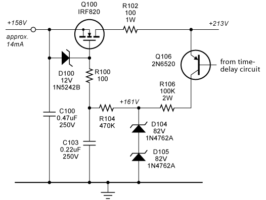
The zener diode D100 and resistors R100 and R102 are necessary for stability and protection. R104 and C103 provide both noise filtering and a slow turn-on. Q106 is driven by a time delay circuit that kicks in about 45 seconds after main power is applied.
This circuit is what I call a "low-gain" regulator - it depends on just the transconductance of the MOSFET for its performance. Since it is low-gain, it should not be shared between channels or between high and low-level stages. However, it sounds pretty good! I've found that adding a lot of gain in this type of regulator, especially an op-amp tends to make the overall amplifier sound "solid-state", i.e. hard and cold.
This is not an original circuit - I got the idea for this from the old MFA preamps, where this circuit was called a "buffer". It works well, and with the protection devices shown, is quite reliable. If the output is accidently shorted, resistor R102 blows. It should be a metal oxide "flame-proof" type.
- John Atwood
I'm a little late to this thread, but thought you would be interested in what we do in the Artemis Labs preamps. Attached is a fragment of the schematic of the LA-1 line amp. It is the B+ regulator, for one channel. The zener diode reference string is shared between channels. The exact same circuit is used in the PH-1 and PL-1 phono preamps.
The zener diode D100 and resistors R100 and R102 are necessary for stability and protection. R104 and C103 provide both noise filtering and a slow turn-on. Q106 is driven by a time delay circuit that kicks in about 45 seconds after main power is applied.
This circuit is what I call a "low-gain" regulator - it depends on just the transconductance of the MOSFET for its performance. Since it is low-gain, it should not be shared between channels or between high and low-level stages. However, it sounds pretty good! I've found that adding a lot of gain in this type of regulator, especially an op-amp tends to make the overall amplifier sound "solid-state", i.e. hard and cold.
This is not an original circuit - I got the idea for this from the old MFA preamps, where this circuit was called a "buffer". It works well, and with the protection devices shown, is quite reliable. If the output is accidently shorted, resistor R102 blows. It should be a metal oxide "flame-proof" type.
- John Atwood
John,
Thanks, what you have posted is exactly what I have in mind (apart from Q106). I plan to get my delay by making R104 about 2.2Meg and C103 around 1uF, high quality cap, What I was describing to SY and Carlos is replacing D104 and D105 with a resistor and R106 with a CCS.
Thanks, what you have posted is exactly what I have in mind (apart from Q106). I plan to get my delay by making R104 about 2.2Meg and C103 around 1uF, high quality cap, What I was describing to SY and Carlos is replacing D104 and D105 with a resistor and R106 with a CCS.
MOSFET regulator impedance
Brian -
I don't have output impedance numbers at hand for the IRF820 regulator. However, in the next day or two I will be testing a new Artemis Labs power amp (push-pull 2A3s) that uses this same regulator circuit for the driver stage. While it is on the test bench, I'll run a sweep of regulator output impedance vs frequency, and post the results here.
- John
Brian Beck said:John,
Any idea what the IRF820's transconductance is at 14mA? Or, asked another way, what is the power supply's output impedance? The data sheet shows only large currents, of course, and the curves appear almost cut-off where 14mA would be.
My MOSFET follower power supply has the output impedance about 20ohms with 20-25mA load. Measured with fixed 20mA, and modulated 5mA load, with scope. I used IRF 720 in the regulator.
sajti
Re: Series Mosfet regulator
John;
I would call it "A miracle", since it is a meaningless mess made of details.
JohnAtwood said:
This circuit is what I call a "low-gain" regulator
John;
I would call it "A miracle", since it is a meaningless mess made of details.
Brian Beck said:John,
Any idea what the IRF820's transconductance is at 14mA?
Why do you think that HEXFET of N-type with negative voltage on drain will conduct 14mA?
MOSFET source-follower results
Here are the results from some tests I did on the Artemis Labs DP-2 MOSFET regulator. This circuit is identical to the earlier schematic diagram for the LA-1, except that the input voltage is about 345V, the output voltage (and associated zener diode string) is 245V and R106 is 150K.
I first put a constant-current load on the regulator (disconnecting the regulator from the amplifier load), then modulated this current with an AC sine wave. I can do this through a special voltage-controlled current sink that I built for testing power supplies. I tried three cases: 10, 20, and 40mA. The AC modulating signal was constant at 2.5mA rms. The Audio Precision was connected to the regulator output and the AC voltage measured as the frequency was swept from 10Hz to 100KHz. At 1KHz, the following AC voltages were measured, and the implied regulator output resistance given:
10mA - 54.5mV --> 21.8 ohms
20mA - 32.7mV --> 13.1 ohms
40mA - 21.2mV --> 8.5 ohms
As expected, the regulation gets better with higher DC current, since the transconductance of the MOSFET increases. The good news is that the output impedance is virtually flat from 20Hz to around 10KHz, where it starts to drop, likely due to the 0.47uF capacitor at the output. I have found that power supplies that have a flat output impedance across the audio band sound the best.
Then, I decided to test line regulation. I did this by supplying the regulator from a bench supply with a 1K ahead of the regulator. I used my voltage-controlled current sink at the output side of the 1K resistor to make a 5Vrms signal riding on top of the 345VDC input to the regulator. Here is the resulting AC output voltages for two different DC current loads:
10mA - 2.63mV --> -65.5dB
20mA - 2.84mV --> -65.0dB
The dB numbers are the amount of filtering. In this case, the current doesn't matter too much. The filtering is constant over the audio band, although it gets worse below about 25Hz - perhaps due to the time constant of the 470K and 0.22uF capacitor.
The filtering isn't perfect and neither is the regulation, but they are decent and constant over frequency.
- John Atwood
- Status
- This old topic is closed. If you want to reopen this topic, contact a moderator using the "Report Post" button.
- Home
- Amplifiers
- Tubes / Valves
- Series MOSFET regulator better with just voltage ref on gate or with error amp?