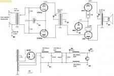
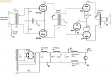
I have been playing with 2A3 pp designs to compare to a 2A3 PSE amplifier that my son is building. I have come up with this design and I would like your views on how it might be improved, whether its rubbish or not, suggested component choices, etc. etc.
Basically any help or critisim you care to give...
Thanks
James D.
Basically any help or critisim you care to give...
Thanks
James D.

John,
Thanks for the rminder. I did forget that the first time! But know it says my picture size is too big and must be under 800x1200. But my image size is under that....
I'll try again and see what happens. It might be finger trouble as I'm mildly dyslexic and that can affect my typing...
lets see if it attaches here ...
James
Attachments

[insert expletive] Microsoft!
James,
I had a long reply in the process when IE crashed and took out the 'puter. So here's a synopsis;
Diode bias; never tried it, most people I have corresponded with about it didn't like it for a variety of reasons. However, it's only a resistor and a cap to change. There's info on this at Steve Bench's pages.
Fixed bias 6C45: My (limited) experience with biassing direct on line level tubes has been a bit uninspiring. However, other's like Joel like it. Frank has suggested bypassing the battery with some good polypro's. Again a couple of resistors makes it cathode bias. I'd suggest trying both for a while once it's built. Ditto for the diode biassed OP stage. You <i>might</i> need to put input caps, as some of the TVCs are very sensitive to any DC bias or offset. (I use S&B TX102/2)
The op point on the 6C45's at Va=175V and Vg=-2.5V shows about 15mA Ia. The anode voltage is a bit above the 150V max rating on the sheet, but I onow of people who've run them at 5W+ at 250V for long periods. Tough little beast.
Tubes: Matched sets of 2A3 (easy & cheap with Sovteks), and especially 6C45's as they vary a LOT sample to sample IME. I like them though, and they're nice and grunty, driving 300Bs well so a 2A3 should be a piece of ****. Sound good too.
Driver gain will be around 50, with an input sensitivity of 800mV or so.
Grid stoppers <b>required</b> on the 6C45s.
Signal Iron: There isn't any need to spec them for the current, except perhaps for the IT, where an imbalance of 5mA or so should be allowed for even with well matched toobs. My suggestion would be a Lundahl LL1635/5mA or similar. Any quality PP OPT will be fine. No significant airgap is neccessary, construction butt gaps are plenty. It'll lower the inductance lots for no benefit.
PSU: I like, no significant quibbles. The chokes are rated higher for current than they need to be. No problem with this, but it might save some $ and weight with smaller ones.
Suggested addition would be a glow diode shunt reg for the driver stage.
My fave writer and experimenters with PP DHT are <a href="http://www.nutshellhifi.com/triode1.html">Lynn Olson</a> and Gary Dahl. Lots of good stuff in the <a href="http://www.nutshellhifi.com/library/index.html">Library</a>
HTH
Cheers
Brett
SYMBOLS
Hi,
I think there is one already...James used a neon symbol in the diagram though.
Correct me if I'm wrong.
Cheers,")
Hi,
Suggested addition would be a glow diode shunt reg for the driver stage.
I think there is one already...James used a neon symbol in the diagram though.
Correct me if I'm wrong.
Cheers,
Brett, many thanks - MS no thanks
Brett,
Many thanks for your detailed reply. I really appreciate it. I would have loved to read your initial response... c'est la vie...
I haven't tried valve diode bias myself but I don't like electrolytics in the signal path so it seemed worth trying! I do like battery bias on line stages so it seemed a good idea for the front end! I've not used the 6C45pi but wanted to try it - fall back is the ECC99. I was aiming for about 20mA current maybe I should go for a 2V lead acid cell for bias but that will give me nearer to 40mA (I think...) but thats why I went for 50mA iron in the middle - I like to over specify the iron. Thanks for the grid stopper remark, I'll add them.
As Frank observed the neon symbol was supposed to be a voltage regulator...back to the drawing board.
Indeed Lynn Olsen and Gary Dahl have been part of the inspiration for this.
Thanks again for the reply.
ciao
James
One big problem is that you can't adjust the idle current of the output stage. If whatever saturation voltage the rectifier gives you isn't the right one, you're hosed. Unlike a cathode resistor, this isn't self correcting as the tubes age. You'll also get some interesting nonlinearity from that rectifier, though the P-P topology will cancel much of the even-order stuff.
Why not just use a fixed bias source? Sure, it's boring and conventional, but it WORKS. So do cathode resistors, albeit at a lower efficiency.
And 2A3s aren't that tough to drive- why not get rid of that big hunk of magnetic stuff in the middle and use a proper driver stage? Everyone seems to freak out if there's the tiniest bit of nickel or steel in a resistor end-cap, then they run their signal through a magnetic circuit! I don't have the 2A3 curves in front of me, but at under 300V on the plate, I can't imagine that you'd need more than 90V peak to peak to run them full bore. I've used them in a ST-70 with a plain vanilla 6SN7 diff amp driving them with no problem.
The fixed versus auto bias seems to be a very subjective preference. I do like fixed bias in preamps, could possibly live with it with a SE 2A3, but really hate it in PP EL34/84.
2A3 is not easy to drive. If you drive it properly (6L6 or similar triode strapped, choke or transformer loaded) it can show real power and depth.
cheers
peter
2A3 is not easy to drive. If you drive it properly (6L6 or similar triode strapped, choke or transformer loaded) it can show real power and depth.
cheers
peter
analog_sa said:2A3 is not easy to drive.
Peter,
What do you mean, specifically, when you say that?
The sound of a 2A3 is a true reflection of the sound of its driver. Use a wimpy driver, enjoy wimpy sound. I have experimented with lots of driving tubes/topologies and have noticed that the universally accepted ECC83/6SL7/6SN7 RC coupled schemes don't produce particularly exhilarating sound. Don't know if the tube is particularly difficult to drive objectively, with regards to input capacitance/grid current , nor do i care.
peter,
a self-admitted subjectivist
peter,
a self-admitted subjectivist
Reducing both the output impedance of the driver to values much lower than what's minimally required and providing a low dc impedance from output tube grid to ground sounds better to me. I wouldn't know what's a 'valid' listening test anyway. The only opinions i unreservedly trust always come from my own ears
- Status
- This old topic is closed. If you want to reopen this topic, contact a moderator using the "Report Post" button.
- Home
- Amplifiers
- Tubes / Valves
- Push pull dht triode with diode bias