Hi all,
We've seen lots of great projects here where we've developed PCB's and did a group buy. So, I'm working on a simple (non-regulated) HV supply PCB for our projects and would like input. Maybe do a GB?
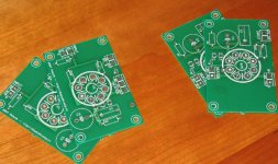
I have a couple of prototypes made and they are pretty sweet!
Here are some pics:
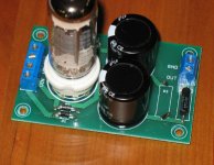
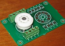
Component side w/socket
Component side, sans socket
Solder side
And the W.I.P. documentation for this:
docs_in_progress.pdf
What do you think so far?
Cheers!
We've seen lots of great projects here where we've developed PCB's and did a group buy. So, I'm working on a simple (non-regulated) HV supply PCB for our projects and would like input. Maybe do a GB?
I have a couple of prototypes made and they are pretty sweet!
Here are some pics:
Component side w/socket
Component side, sans socket
Solder side
And the W.I.P. documentation for this:
docs_in_progress.pdf
What do you think so far?
Cheers!
Is there ever a standard PSU? If you make the assumption that you use a single octal rectifier and electrolytics, then what about all those that use motor runs, twin damper diodes and noval sockets for EZ80/81? We haven't even started on glow tubes.
What geek has will allow for different situations. Granted not everything someone could dream up power supply wise. Your motor run capacitors could be fed off the board and mounted near the board by using feed wires. Glow tubes could be fed from the power supply board also.
The design has merit.
I would add an additional mounting hole at the center - this would give better support to the rectifier socket. You might also want to add 2W bleeders.
For a voltage doubler, it's the same as the split supply if you're using series pairs of caps - just hook the transformer to AC and ground. By the way, I have a pretty much unlimited supply of 270/315V and 470/250V snap-ins... from nearly new scrap boards where I work.
For a voltage doubler, it's the same as the split supply if you're using series pairs of caps - just hook the transformer to AC and ground. By the way, I have a pretty much unlimited supply of 270/315V and 470/250V snap-ins... from nearly new scrap boards where I work.
Why would you want to use a PCB with tubes?
After many tube insertion-pulls you're gona weaken the traces. You're also gona manufacture a swell capacitor around some of the grid leads. I vote for hand wiring in spades like the Tektronix scopes of the late 60s! For solid state it's great!
After many tube insertion-pulls you're gona weaken the traces. You're also gona manufacture a swell capacitor around some of the grid leads. I vote for hand wiring in spades like the Tektronix scopes of the late 60s! For solid state it's great!
Re: Why would you want to use a PCB with tubes?
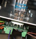
Not if you do it right. I use daughter boards on tube sockets, but the trick is to use the socket itself for mounting. Thus, there is no stress on the board. Here's one installed.
grhughes said:After many tube insertion-pulls you're gona weaken the traces.
Not if you do it right. I use daughter boards on tube sockets, but the trick is to use the socket itself for mounting. Thus, there is no stress on the board. Here's one installed.
Attachments
And, here's a little PS in the same spirit as the thread starter's. All of the parts can be mounted on the bottom as well to allow for the same style of chassis mounting. I also have an octal version. I tend to use one of these as a starter, with some higher quality caps or a regulator after. But, it is great for breadboarding.
Attachments
Re: Re: Why would you want to use a PCB with tubes?
Doug,
Did you make (or have made) those boards? I would like to get some boards for octal and noval tubes with screw terminals like that for experimenting!
dsavitsk said:
Not if you do it right. I use daughter boards on tube sockets, but the trick is to use the socket itself for mounting. Thus, there is no stress on the board. Here's one installed.
Doug,
Did you make (or have made) those boards? I would like to get some boards for octal and noval tubes with screw terminals like that for experimenting!
Re: Re: Re: Why would you want to use a PCB with tubes?
If you haven't seen it, you can get an "octal relay" from tubesandmore.com that has screw terminal connections to each pin
I searched around and could not find a noval version, so I made my own.
Sherman said:Did you make (or have made) those boards? I would like to get some boards for octal and noval tubes with screw terminals like that for experimenting!
If you haven't seen it, you can get an "octal relay" from tubesandmore.com that has screw terminal connections to each pin
An externally hosted image should be here but it was not working when we last tested it.
I searched around and could not find a noval version, so I made my own.
Attachments
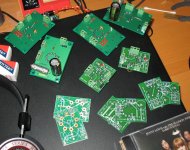
I did have them made. I found a board house that will allow me to panelize a bunch of stuff onto one large board. I also discovered that I like designing boards a lot more than I like soldering, so I just keep making them.
Anyhow, I have a pair each of 6sn7 and 6j5 boards that I am not going to use that you are welcome to. The caveats are 1. the spacing is only 8mil, which is maybe a little close for really high voltages, so you would need to be careful, 2. I've not tested them to know that they are good for anything, and 3. the reason I've not tested them is that I stupidly relied on the Eagle tube library before i knew better. The socket pin spacing is not quite right. If you can find a very small octal socket, you might be able to cram it in. I have done this, and it is kind of possible but it is a bit of a pain.
Each board can be biased via a resistor and cap, or via LED.
Attachments
Hi guys,
Snap-in caps will fit. Radial leaded too, but not perfectly flush.
Super ideas, thanks!")
For solderless experimenting with tubes, there are these for breadboards
SvErD said:Good idea! Is it snap-in size caps you have designed for?
Snap-in caps will fit. Radial leaded too, but not perfectly flush.
Tom Bavis said:I would add an additional mounting hole at the center - this would give better support to the rectifier socket. You might also want to add 2W bleeders.
Super ideas, thanks!
For solderless experimenting with tubes, there are these for breadboards
An externally hosted image should be here but it was not working when we last tested it.
Just some afterthoughts...
If solder does not melt from socket tags fitted on chasis how it is going to melt from PCB pads ? Have you see solder dipping from PCB fitted with tubes? The PCB chosen is glass epoxy board FR4 material can withstand very high tempratures.
http://en.wikipedia.org/wiki/FR-4
Plus a couple shots of another great prototyping method using sockets, standoffs and tagboard! Getting more ideas into the field here.
Wavebourn said:I don't like to solder tube sockets to PCBs, despite it looks nice and is more technological hot metals are expanding in size and all gear needs to be periodically switched off so sooner or later the solder gets loose.
If solder does not melt from socket tags fitted on chasis how it is going to melt from PCB pads ? Have you see solder dipping from PCB fitted with tubes? The PCB chosen is glass epoxy board FR4 material can withstand very high tempratures.
http://en.wikipedia.org/wiki/FR-4
Plus a couple shots of another great prototyping method using sockets, standoffs and tagboard! Getting more ideas into the field here.
An externally hosted image should be here but it was not working when we last tested it.
An externally hosted image should be here but it was not working when we last tested it.
Re: that's cool
Thanks much!
It's also very rugged (wasn't planned that way, it just is). Speaking of 6550's, you could build a tank of a guitar amp this way, no doubt.
opik said:this is so cool i think it's a good idea, cos personally i don't like too many cables on my design, Nice works!Geek
I've seen Audio Research VT100 inside there was 8 of 6550 it's build in using pcb, and less cables..
Thanks much!
It's also very rugged (wasn't planned that way, it just is). Speaking of 6550's, you could build a tank of a guitar amp this way, no doubt.
- Status
- This old topic is closed. If you want to reopen this topic, contact a moderator using the "Report Post" button.
- Home
- Amplifiers
- Tubes / Valves
- Developing a "universal" tube power supply PCB