El84+ef86
i am going to build this amp, which designed by mullard.
http://www.bonavolta.ch/hobby/en/audio/el84_3.htm
do you have any comment? is the gain too high at the gain stage?
i am going to build this amp, which designed by mullard.
http://www.bonavolta.ch/hobby/en/audio/el84_3.htm
do you have any comment? is the gain too high at the gain stage?
I think I prefer version 4: http://www.bonavolta.ch/hobby/en/audio/el84_11.htm
This one looks very nice if you can do without the EF86 and global negative feedback: http://www.jogis-roehrenbude.de/Leserbriefe/Goecking-EL84SE/Goecking.htm
My
This one looks very nice if you can do without the EF86 and global negative feedback: http://www.jogis-roehrenbude.de/Leserbriefe/Goecking-EL84SE/Goecking.htm
My
do you have any comment?
http://home.att.net/~chimeraone/mullardampinfo.html
A few observations:
- very exotic operation of the ef86 does the gain-gaining trick; I doubt if it sounds as good as a more conventional working point
- recipe for humm-disaster power supply (must be substituted)
- tone controls? (can be left out)
- complicated NFB loop (can be ammended)
- DC-coupling sounds interesting
I haven't heard the mullard 3.3 but to give a sense of horizon here are some options that give/promise excellent results using the magical ef86/el84 combo:
- Triode-wire the output stage (if 1.5 watts is enough for you, no NFB; 270V@ 35mA sounds great for el84 or 300v@45mA for max. power; 230 to 250V @ about 1.5 mA for the ef86). This will give you a creamy, sluggish, romantic sound. Insert bypassed zeners between screen and anode and you've got the best of both worlds (pentode slam and no feedback triode midrange).
- Use partial feedback as Dave did (lets you use the ef86 at a more normal working point)
- Use another input tube e.g. ecc83; decware has an online schematic of their el84 pentode SE: http://www.decware.com/newsite/mainmenu.htm
Simon
Re: El84+ef86
Hi takashi. I built a version of that circuit and eventually replaced it with my own design. Some quick comments:
- Gain is indeed high, 0.1 volt for full power as I recall.
- That circuit appears in two versions, in the alternate (from memory) R9 = ~ 1meg and C4 = ~0.1 uF and ties to the output cathode instead of ground.
- Though my build of that circuit measured about 0.1% THD for 1 watt the distortion was heavily weighted towards higher harmonics. I could never cure a particular 'sharpness' in sound and eventually looked elsewhere
- Klimon's recommedation for bias and connection agree with my experiences, except I prefer ~50 volts higher B+ with certain brands (mainly the Russians.)
takashi said:i am going to build this amp, which designed by mullard.
http://www.bonavolta.ch/hobby/en/audio/el84_3.htm
do you have any comment? is the gain too high at the gain stage?
Hi takashi. I built a version of that circuit and eventually replaced it with my own design. Some quick comments:
- Gain is indeed high, 0.1 volt for full power as I recall.
- That circuit appears in two versions, in the alternate (from memory) R9 = ~ 1meg and C4 = ~0.1 uF and ties to the output cathode instead of ground.
- Though my build of that circuit measured about 0.1% THD for 1 watt the distortion was heavily weighted towards higher harmonics. I could never cure a particular 'sharpness' in sound and eventually looked elsewhere
- Klimon's recommedation for bias and connection agree with my experiences, except I prefer ~50 volts higher B+ with certain brands (mainly the Russians.)
It's not a completely DC coupled circuit. The EF86 is grid-leak biased, which means the front end coupling cap and 10 meg grid resistor (C1 and R3) are mandatory. A DC coupled driver has advantages under clipping for sure though. Since the EF86 operates at such low currents and in grid leak bias it will be difficult, if not impossible, to get anything of value from the typical published plate curves without knowing the operating voltages. Spice models for the EF86 don't capture grid leak bias either, but you can get an approximation by using (from memory) about 1/2 volt negative fix bias on the front end via the 10 meg resistor.
It's a very unconventional circuit which I'm guessing the Mullard engineers developed more on the bench than with a slide rule.
It's a very unconventional circuit which I'm guessing the Mullard engineers developed more on the bench than with a slide rule.
i just calculate, Ik = Ig2 +Ia, and the 5K inductor loading seems to be short circuit in DC. so if Vk = 28V, Rk =560, the Ik = ~50ma, and i find the spec, Ig2 is arround 5ma, so the Ia is arround 45ma.... am i wrong?
in fact, i am assume the supply Voltage of the EL84 is 300V. and i can get the graph of 300v Va and Vg2 at the datasheet. but i dont know how to get the Q point. and also, can i assume the Vgk is -8V? since the Vg1 is 20V and Vk is 28V....
yes, it is a DC coupling AMP, the Va of the EF86 is 20V.
from the web, i find that it is a 3W amplifier, how to calculate the 3W?
Not bad! I found my old measurements of this circuit. For the EF86, Va = 19 Vdc, Vg2 = 27.6 Vdc, Vg1 = -0.76 Vdc and Vk = 0.027 Vdc. Unfortunately I didn't note which value of R4 was used. Note Vg1, that's what I mean by this circuit not being completely DC-coupled. The first capacitor is mandatory to properly bias the EF86. For the EL84, Va = 295 Vdc, Vg2 = 282 Vdc, Vg1 is of course 19 Vdc and Vk = 28.6 Vdc. B+ was 315 Vdc (different power supply than recommended) and the output transformer had ~ 420 ohm primary DC resistance.
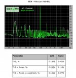
By lucky coindicence I stumbled on measurements I took of this circuit while looking for a manual. I think the attached distortion plot was for 1 watt out but don't have a record. As mentioned above, the numerical THD was great but the spectrum of harmonics not so much. Hope yours turns out better.")
I just remembered! The stock time constants for C4 and C8 cause the bass to roll off fast below 50 Hz. This is clearly visible in the original article, Fig. 3. Since these caps are also part of the feedback loop to the EF86 screen extending LF response is tricky. I no longer recall what values I ended up with but the readings have C4 = 330uf and C8 = 100 uF scribbled on it. Your best bet is to tweak in circuit.
By lucky coindicence I stumbled on measurements I took of this circuit while looking for a manual. I think the attached distortion plot was for 1 watt out but don't have a record. As mentioned above, the numerical THD was great but the spectrum of harmonics not so much. Hope yours turns out better.
I just remembered! The stock time constants for C4 and C8 cause the bass to roll off fast below 50 Hz. This is clearly visible in the original article, Fig. 3. Since these caps are also part of the feedback loop to the EF86 screen extending LF response is tricky. I no longer recall what values I ended up with but the readings have C4 = 330uf and C8 = 100 uF scribbled on it. Your best bet is to tweak in circuit.
Attachments
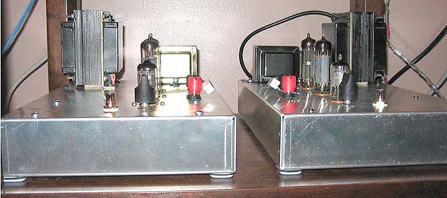
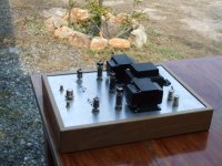
el84+ef86se triode connect.
I am build el84se triode mode.
http://www.htg2.net/index.php?topic=29952.0
it is a very sweet tube dirver.
275V@ 35mA sounds great for el84 .
230 to 250V @ about 1.5 mA for the ef86
This will give you a creamy, sluggish, romantic sound.
Regards.
Dikky..
I am build el84se triode mode.
http://www.htg2.net/index.php?topic=29952.0
it is a very sweet tube dirver.
275V@ 35mA sounds great for el84 .
230 to 250V @ about 1.5 mA for the ef86
This will give you a creamy, sluggish, romantic sound.
Regards.
Dikky..
Attachments
Hi Klimon,
If you are interested to have a look, I plotted EF86 characteristics as per op point used in the Mullard 3-3 circuit, see: EF86 characteristics at low screen and anode voltage which is quite linear. More linear than most of the "usual" op points, I would say.
Regards,
Tom Schlangen
Klimon said:http://home.att.net/~chimeraone/mullardampinfo.html
A few observations:
- very exotic operation of the ef86 does the gain-gaining trick; I doubt if it sounds as good as a more conventional working point
If you are interested to have a look, I plotted EF86 characteristics as per op point used in the Mullard 3-3 circuit, see: EF86 characteristics at low screen and anode voltage which is quite linear. More linear than most of the "usual" op points, I would say.
Regards,
Tom Schlangen
- Status
- This old topic is closed. If you want to reopen this topic, contact a moderator using the "Report Post" button.
- Home
- Amplifiers
- Tubes / Valves
- EL84 + EF86