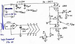
Attached below is a 6SN7 Variant of the Kurt Strain Headphone amp
I entered the values for the psu into psud 2 and only got 160 volts or so
When I lower the R value to 1k I get into the 300 V range like the schematic.
My problem is that I don't know the current draw of the circuit under a 250 Ohm load
Also I would like to use a tube rectified psu instead of solid state. I know that I have to lower the C1 value to 35uf. Is it ok to raise the value of C2 to 200uf in order to lower the ripple?
I just need some ideas on how to change the PSU to tube and how to input those values into psud?
Attachments
Hi sbelyo ,
One question : There is ONE power supply like that
for each channel , or ONLY one power supply for the
two channels ??
Assuming that you will use the same power transformer
and assuming what you said , the “apparent” current of
one channel is about 45 mA , ( apparently you are
wasting aprox. 45 V on the 1K resistor ) and being so ,
you can use a tube rectifier BUT with a LC filter and
not with a RC filter like now .
You are correct , you have to lower C1 value to 33 uf
and CAN raise C2 value to 220 uf ( with a 10 – 15 H
choke ) . The correct proceeding , is to repeat the set
10 – 15 H choke + C2 ( 220 uf ) for the other channel ,
so you can get the maximum stereo effect .
( your PSU will be very expensive ) .
With a rectifier tube , the voltage value on C1 will be
aprox. 315 VCC ( under load ) , so there is no margin
to waste voltage on the resistor of a RC filter .
RC filter with resistor value lower than 1K , doesn’t work
properly for low currents like 45 mA . Then you need
to use a choke , BUT in my humble opinion you will
raise the ripple .
If you are worried about “cathode stripper “ due to
the fast voltage raise on the plate , you can use a stand-
by switch . If you want to hear the “sonic difference” , go
ahead !!
Don’t worry about the current draw with a 250 ohms load
because you have a 220 uf capacitor to supply the instan-
taneous demand of music .
Another important advice : With a 6.3 VAC secondary
winding and a bridge rectifier , you will not get a 6.3 VCC
after the 4700 uf filter capacitor , the final voltage
( under load ) will be a bit lower , and , with a high level
ripple . For a perfect and well filtered 6.3 VCC , you need
a ~ 9 VAC secondary winding , at least .
Best Regards ,
Carlos
Hi sbelyo,
what puzzles me in your post is that the original schematic on headwize says nothing about 300V but 250V instead...??
Otherwise I assume that you are using one PSU to drive both channels...
I quickly simulated the original psu in PSUD2 and came to current draw of about 45mA (BOTH channels). Using that number and playing in PSUD you can quickly see how different values of components behave...
When you insist on running at 300V your choice of transformer is ok, and using a 5AR4 as rectifier tube, a small 2,2uF first cap (which can be tuned to get the desired voltage), a choke with about 160ohms and second C of 100uF you arrive at about 300V. But i'm afraid that ripple suppression is not enough for headphone use so I would add another RC stage with 220R and 100uF. Increasing the value of the second cap is no problem (i.e. 470uF).
In general tube rectifiers have a voltage drop of 30 to 60 volts, so your choice of trans is different than using ss diodes.
My only experience in designing psu's comes from building my c3g-headphone amplifier (see gallery very recently) that uses a tube rectified psu with 5R4, two chokes and only mkp capacitors.
I played around for quite some time, but in fact the amplifier is dead silent...
In contrast to refference' suggestion I also arrived at 6.3V for the heaters from a 6.3V tap. The heater psu is a bridge rectifier followed by a 10000uF cap and an RC stage with 0R22 and another 10000uF cap.
Good luck,
Oliver
refference said:Hi sbelyo ,
One question : There is ONE power supply like that
for each channel , or ONLY one power supply for the
two channels ??Carlos
I think that is for both channels. I built a van waarde design that had only one PSU for both channels and it works fine.
That sounds like a planrefference said:Assuming that you will use the same power transformer
and assuming what you said , the “apparent” current of
one channel is about 45 mA , ( apparently you are
wasting aprox. 45 V on the 1K resistor ) and being so ,
you can use a tube rectifier BUT with a LC filter and
not with a RC filter like now .
I'm not that concerned with price. I would like to build what you mentioned above to see if I can hear the difference.refference said:You are correct , you have to lower C1 value to 33 uf
and CAN raise C2 value to 220 uf ( with a 10 – 15 H
choke ) . The correct proceeding , is to repeat the set
10 – 15 H choke + C2 ( 220 uf ) for the other channel ,
so you can get the maximum stereo effect .
( your PSU will be very expensive ) .
I was told that the rectifer tube has a slow startup to begin with so that should be fine without a soft startrefference said:If you are worried about “cathode stripper “ due to
the fast voltage raise on the plate , you can use a stand-
by switch . If you want to hear the “sonic difference” , go
ahead !!
Don’t worry about the current draw with a 250 ohms load
because you have a 220 uf capacitor to supply the instan-
taneous demand of music .
I might try the heaters on AC and ground one leg with a resistor.refference said:Another important advice : With a 6.3 VAC secondary
winding and a bridge rectifier , you will not get a 6.3 VCC
after the 4700 uf filter capacitor , the final voltage
( under load ) will be a bit lower , and , with a high level
ripple . For a perfect and well filtered 6.3 VCC , you need
a ~ 9 VAC secondary winding , at least .
Best Regards ,
Carlos [/B]
Stixx said:Hi sbelyo,
what puzzles me in your post is that the original schematic on headwize says nothing about 300V but 250V instead...??
I dug that schematic up from someone that had a website with a revised build using the 310V
Originally posted by Stixx Otherwise I assume that you are using one PSU to drive both channels...
I quickly simulated the original psu in PSUD2 and came to current draw of about 45mA (BOTH channels). Using that number and playing in PSUD you can quickly see how different values of components behave...
So it's 45ma for 2 channels then. Should I give each channel it's own filter network?
Hi sbelyo,
No, there is no need to give each channel its own filter network. When you want to do that (for better channel separation) I would start with two transformers and so on...
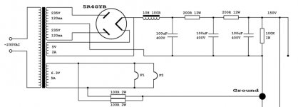
As an example I can show you the schematic for another headphone amp I was planning and where I somewhat modified the psu (incidentally also the vanwaarde amp...) ;-)
It is just for illustration how I started to design a psu...in this case it's LCRCRC with a choke first. As i said you can simulate everything in PSUD2...
EDIT: in the schematic you can see how it splits up at the end for the other channel...
rgds,
Oliver
No, there is no need to give each channel its own filter network. When you want to do that (for better channel separation) I would start with two transformers and so on...
As an example I can show you the schematic for another headphone amp I was planning and where I somewhat modified the psu (incidentally also the vanwaarde amp...) ;-)
It is just for illustration how I started to design a psu...in this case it's LCRCRC with a choke first. As i said you can simulate everything in PSUD2...
EDIT: in the schematic you can see how it splits up at the end for the other channel...
rgds,
Oliver
Attachments
sbelyo said:I might try the heaters on AC and ground one leg with a resistor.
If the heater secondary has a center tap, try just connecting that to your star ground. If it doesn't, create one with a couple of resistors (~20R) and ground that center tap.
sbelyo wrote :
Should I give each channel it's own filter network?
Hi sbelyo ,
The answer is : YES
Using diodes : After C1 ( 220 uf ) split the power supply in two
RC network one for each channel ( You can raise C2 to
220 uf / channel ) . The R value ( of RC filter ) must be adjusted
for ~ 310 V at the filter output ( C2 for each channel ) .
Using a tube rectifier : After C1 ( 33 uf ) split the power supply in
two LC network one for each channel ( L ~ 10 – 15 H and
C2 = 220 uf / channel ) .
Doing so , you will be able to get the BEST stereo effect , and
a ultra-low level ripple , and as a “bonus” , a ultra soft start , in-
creasing the tube’s life expectancy .
There is no necessity to have one power transformer for each
channel , because the 220 uf ( C2 for each channel ) is almost
a short circuit from the point of view of an audio signal , so one
channel will be extremely well isolated from another . As you
can see , is important to have one RC or LC filter network for
each channel , because the channel separation will be the BEST .
About the heater supply , you can follow the Stixx’s suggestion
BUT that even the voltage output reaches a value around 6 VCC,
you can be sure that the regulation will be very poor and the
ripple’s level will be high .
Regards for all ,
Carlos
When I split it in two after C1, what should the values in PSUD be to reflect 2 chokes, 2 C2's etc. ?refference said:
Using a tube rectifier : After C1 ( 33 uf ) split the power supply in
two LC network one for each channel ( L ~ 10 – 15 H and
C2 = 220 uf / channel ) .
Well we have a bit of guesswork here since we don't know the exact current draw of YOUR schematic using higher voltage.
But to simulate the whole thing in PSUD the values stay the same since you are simulating only one channel but retaining total current draw as your input number...
The safest thing to do using a tube rectifier would be to build a CLCRC network with a smallish first cap (otherwise your voltage will be way too high), a choke followed by the second cap of, let's say 220uF, and an RC stage with a third cap of 100uF. Now you can also finetune the resistor value to arrive at your desired voltage...and you have the chance of splitting up after the second cap and build an RC stage for each channel (saves you money...).
Just plug it in in PSUD and make your choice")
rgds,
Oliver
But to simulate the whole thing in PSUD the values stay the same since you are simulating only one channel but retaining total current draw as your input number...
The safest thing to do using a tube rectifier would be to build a CLCRC network with a smallish first cap (otherwise your voltage will be way too high), a choke followed by the second cap of, let's say 220uF, and an RC stage with a third cap of 100uF. Now you can also finetune the resistor value to arrive at your desired voltage...and you have the chance of splitting up after the second cap and build an RC stage for each channel (saves you money...).
Just plug it in in PSUD and make your choice
rgds,
Oliver
Attachments
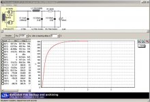
That's exactly what I did last night with PSUD. I got the ripple down very low with a voltage around 310V so I'm going to go with that.Stixx said:The safest thing to do using a tube rectifier would be to build a CLCRC network with a smallish first cap (otherwise your voltage will be way too high), a choke followed by the second cap of, let's say 220uF, and an RC stage with a third cap of 100uF. Now you can also finetune the resistor value to arrive at your desired voltage...
Now, in the amplifier section I don't know what wattage I should use for the resistors. Are 2 that are labeled 2 Watt but I don't know what to use for the rest?
Now, in the amplifier section I don't know what wattage I should use for the resistors. Are 2 that are labeled 2 Watt but I don't know what to use for the rest?
I can see only one since you are loosing the first resistor in the psu and putting in a choke instead...but the resistor of the RC stage can be 2W also to be on the safe side.
As far as I can see 0.5W should do okay for the rest...
cerrem said:To calculate the cap size for a given low frequency response..
You need to know two R values...
The (2*pi*R*C) is an ideal equation that assumes you have an ideal source, which is never the case...
You need to know the equivelent impedance looking back into the amplifer from before the cap...and then ahead of the cap which you already know as you headphones.. I would use the smallest headphone impedance for the calculation, since anything higher is gravy...
Keep in mind you typically use a -3dB frequency much lower than 20 Hz, the reason is that in audio you are concerned with phase shifting.... Since the Phase shift at -3dB for a -20db/decade slope is 45 degrees, not really good for audio... Drop the freq then examine the phase shift until it is satisfactory.. I personally design for 6Hz or lower to obtain least phase shifting at 20Hz..
Chris
This was a response I got from another user about figuring out the output capacitor value in the amplifier stage.
I'm going to use 60uf for the output cap. My main set of cans are 250 Ohm.
I couldn't even begin to figure out the impedance of the circuit before the cap. Anyone want to take a stab/
- Status
- This old topic is closed. If you want to reopen this topic, contact a moderator using the "Report Post" button.
- Home
- Amplifiers
- Tubes / Valves
- Help with PSU Design