I have never built a "from scratch" tube amp before, but I have modified many. This is my initial layout for the project. As this is my first, I was looking for some input on the layout.
http://curlywoods.com/graphics/layout.gif
http://curlywoods.com/graphics/layout.gif
Attachments
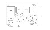
From a mechanical stand point this looks fine. You have T1 on one end and the OPT on the opposite side… all good ideas.
For my personal point of view, I would limit the components on the top of the amp to T1, the OPT, and just the valves.
Is this a stereo amp or mono block?
If it’s stereo, think about building a pair of mono blocks. And if you do build mono blocks, be sure to make them symmetrical!
For my personal point of view, I would limit the components on the top of the amp to T1, the OPT, and just the valves.
Is this a stereo amp or mono block?
If it’s stereo, think about building a pair of mono blocks. And if you do build mono blocks, be sure to make them symmetrical!
Seeing as there's only one OPT, I'd venture a guess that this is a monoblock  . I like the layout but the one recommendation I have is that you leave more elbow room around those KT88's, preferably at least 1" between the glass envelopes and other things, and maybe 1.5" to 2" between the two tubes... otherwise, heat might become a problem. Good luck! Got a schematic for us btw? I like the use of two chokes
 ")
. I like the layout but the one recommendation I have is that you leave more elbow room around those KT88's, preferably at least 1" between the glass envelopes and other things, and maybe 1.5" to 2" between the two tubes... otherwise, heat might become a problem. Good luck! Got a schematic for us btw? I like the use of two chokes Curly,
If I were to nitpick I might recommend seeing if you can move the input/preamp tubes away from the power supply. Better to have your high-signal output stage closer to the PS.
That said, if you are careful with dressing especially AC heater wires your layout would work fine I think.
If I were to nitpick I might recommend seeing if you can move the input/preamp tubes away from the power supply. Better to have your high-signal output stage closer to the PS.
That said, if you are careful with dressing especially AC heater wires your layout would work fine I think.
Thanks guys
Thanks to all for your input.
It is a mono design
I appreciate everyones input. The chokes are alittle too tall for my chassis height to put them under the top. Guess I could rebuild the base (wooden base w/steel top plate) to allow them to fit.
The KT88's were drawn a little oversized by about 3/8" diam. so there will be over 1" between them. The rectifier tube has changed from a 274 to GZ34 type so this is smaller than what I have pictured too.
What is a good distance from the power tranny for input tubes? I am going to orient all tubes so that the heaters are towards the front. I will run the heater wiring along the left side of the base towards the front then to the right along the face of the amp. I am trying to keep the heater wiring well away from the signal paths, as much as possible.
Thanks again for the input. I know I will be asking for assistance before this thing is working
Re: Thanks guys
[
Every amp schematic and every physical layout is a compromise. There are lots of ways to skin a cat. Sometimes we compromise "optimum" layout for aesthetics (at least I do!).
There isn't a specific distance from power supply stuff to input stuff. Just think of the power supply as "dirty" and low power input signals as "clean" and try to keep them away from each other. Farther is better than closer (provided it doesn't complicate heater wire routing etc.).
As I said, my suggestion was more of a nit-pick and I think your layout would work fine.
However... if you want to move things how about moving your bias meter to the left of the left-most KT88 then put your input tubes where the bias meter was. If you do that (even if you don't) you may want to move the input jack from the face of the amp to the top. If the jack is on the front the low-signal input wire has to cross the heater wires. If you put it on the top on the opposite side of the input tube from the heater wires the input won't cross the heater wires.
Keeping your heater wires tightly twisted and tucked up in the corner of the chassis is excellent. Twisting them helps cancel AC radiation and tucking them up in the corner at the top of the amp keeps them out of the way of everything else.
Once again, having said all that I have built amps where the input wire crosses heater wires. I put the input wire low on the chassis and tuck the heater wires up in the corner as you propose. I have also built amps where my input jack was at the back and I had a long run of wire from the jack to the input tube (definitely not a recommended practice ) but by using shielded wire for the input and avoiding crossing the AC heaters and crossing the B+ at a right angle the amps are dead quiet with no hum audible on 93dB speakers.
Bottom line of all this stuff- don't let "analysis paralysis" stop you from building!!!
Edit- Also see if you can find a copy of Morgan Jones' "Building Valve Amplifiers". Great resource for questions like these!
[
Curly Woods said:...
What is a good distance from the power tranny for input tubes? I am going to orient all tubes so that the heaters are towards the front. I will run the heater wiring along the left side of the base towards the front then to the right along the face of the amp. I am trying to keep the heater wiring well away from the signal paths, as much as possible.
...
Every amp schematic and every physical layout is a compromise. There are lots of ways to skin a cat. Sometimes we compromise "optimum" layout for aesthetics (at least I do!).
There isn't a specific distance from power supply stuff to input stuff. Just think of the power supply as "dirty" and low power input signals as "clean" and try to keep them away from each other. Farther is better than closer (provided it doesn't complicate heater wire routing etc.).
As I said, my suggestion was more of a nit-pick and I think your layout would work fine.
However... if you want to move things how about moving your bias meter to the left of the left-most KT88 then put your input tubes where the bias meter was. If you do that (even if you don't) you may want to move the input jack from the face of the amp to the top. If the jack is on the front the low-signal input wire has to cross the heater wires. If you put it on the top on the opposite side of the input tube from the heater wires the input won't cross the heater wires.
Keeping your heater wires tightly twisted and tucked up in the corner of the chassis is excellent. Twisting them helps cancel AC radiation and tucking them up in the corner at the top of the amp keeps them out of the way of everything else.
Once again, having said all that I have built amps where the input wire crosses heater wires. I put the input wire low on the chassis and tuck the heater wires up in the corner as you propose. I have also built amps where my input jack was at the back and I had a long run of wire from the jack to the input tube (definitely not a recommended practice
) but by using shielded wire for the input and avoiding crossing the AC heaters and crossing the B+ at a right angle the amps are dead quiet with no hum audible on 93dB speakers.Bottom line of all this stuff- don't let "analysis paralysis" stop you from building!!!
Edit- Also see if you can find a copy of Morgan Jones' "Building Valve Amplifiers". Great resource for questions like these!
Maybe (probably) you already know but Morgan Jones has two books with confusingly similar titles. "Valve Amplifiers" which has all the goodies required to design and understand tube circuits and "Building Valve Amplifiers" which addresses the physical layout, metal work etc.
Both are worth having.
Both are worth having.
- Status
- This old topic is closed. If you want to reopen this topic, contact a moderator using the "Report Post" button.
- Home
- Amplifiers
- Tubes / Valves
- New amplifier project -my layout