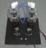
Some exchages with Tubelab have inspired me to build an SE amp similar to his Simple SE design, but using a 6AH6 pentode in triode mode at the input and a 1625 output tube (both extremely cheap and plentiful). I'm using the budget Edcor 5K single ended transformers at the outputs. The unit will be powered with an SMPS of my own design, providing power for both B+ and filaments. the whole shooting match will go in a 6" cube with the tubes poking out on top and the output iron and power supply inside. Finish will be black crackle, with a blue LED pilot light to complement the plate wires. Attached is a picture of the top deck. Next step is to power up the amp with a couple of bench supplies to look for screw-ups and check bias points. After that it's wring out the power supply (built and putting out voltage, but still needing a real going-over and EMI scan), integrate supply and amp, and throw it in the box. Schematic for the amp will follow when I'm sure it's all working.
Attachments
Are you asking for feedback? If not, please ignore the following. If you are, let me suggest that the load CCS on the first stage might be improved for real sonic benefit. The CCS, whatever it is, will leave a sonic footprint in this critical location. I think that the non-linear capacitance behavior of CCSs explains much of the sonic differences between them. Differences in CCS capacitance can be surprisingly audible, even when the RC time constant suggests a pole frequency in the megahertz region, due to minute phase intermodulation effects in the audio band. All this assumes that the low-frequency dynamic resistance of the CCS is very high to begin with, which should be the case here. Specifically, you might consider something to reduce the non-linear capacitive load on the 6AH6’s plate created by Q3’s Ccb through C2 to the B+ supply. If Q3 were a FET, the gate resistance would be so high that you could then bias the gate with very large-value resistors which would provide a series isolating resistance to Cdg. If you insist on using the MJE350, choose a high-hfe MJE350 and try inserting some resistance into the base circuit. Just my two cents…
Noted - nothing comes for free. The MJE350 is there to protect the JFET and stiffen the current source, hopefully increasing its output impedance. Putting a substantial resistance in series with the transistor base would muck up the cascode effect. I may try putting a few kohms in series with the drain, but not until I fire the amp up and see how much voltage swing I have available with the loop closed.
wrenchone said:Noted - nothing comes for free. The MJE350 is there to protect the JFET and stiffen the current source, hopefully increasing its output impedance. Putting a substantial resistance in series with the transistor base would muck up the cascode effect. I may try putting a few kohms in series with the drain, but not until I fire the amp up and see how much voltage swing I have available with the loop closed.
I don't think putting some resistance in series with the drain would help in this circuit. The MJE350's Ccb is still run straight to ground through C2 and Q2 (which is used as a zener I surmise). A HV FET in the place of the MJE350 would allow those large gate resistors with no degradation in cascode performance. Or consider a double (cascode) Supertex DN2540 See the link for performance, which indicates that it presents only 0.177pF to the load.
http://www.pacifier.com/~gpimm/ccs_performance.htm
Once you have this completely ironed out & tweaked nicely, I'd love to see a detailed schematic.
A single-ended 1625 design would be really cool, with the proper
power supply and both pushing it high yet aiming for good full-range audio performance, especially music.
The 1625's with plate caps really look cool, and may do well
if designed for SE, parallel SE, or PP, keeping the components limited and effective (lean).
There are a few 1625 / 807 amps out there but not too common.
I had posted a thread a few days ago about the same subject.
I saw a few last night on a schematics site, like these for example:
http://www.nijnkonijn.nl/machmat/schema/power/ppp/gromm215.gif
http://www.nijnkonijn.nl/machmat/schema/power/ppp/a515amp.gif
http://www.nijnkonijn.nl/machmat/schema/power/ppp/807ab2a1.gif
http://www.nijnkonijn.nl/machmat/schema/power/ppp/807-s.gif
Brian Beck said:If you insist on using the MJE350, choose a high-hfe MJE350 and try inserting some resistance into the base circuit.
Interesting analysis, and easy to overlook these stray capacitances.
What about the possibility of the attached current source? I have even considered replacing the LED with a few series schottky's, which have extremely low capacitance and excellent high frequency behavior.
It would appear to me that the capacitance path you have identified would be mitigated/minimized, yet still keeping the same basic design. I would even think you could reduce the 1uF cap by a factor of 10 and not really affect the performance all that much. LM285 has very low dynamic impedance.
Attachments
Brian, you wrote:
Is the capacitance change under dynamic conditions always proportional to the measured static shunt capacitance, or is it possible that some CCS' with a fairly high Cs display very little dynamic change?
I am very interested phase intermodulation effect and the psycho-acoustic implications. Could you point me in the direction of any papers that have been published on the subject ?
regards
pm
I think that the non-linear capacitance behavior of CCSs explains much of the sonic differences between them. Differences in CCS capacitance can be surprisingly audible, even when the RC time constant suggests a pole frequency in the megahertz region, due to minute phase intermodulation effects in the audio band
Is the capacitance change under dynamic conditions always proportional to the measured static shunt capacitance, or is it possible that some CCS' with a fairly high Cs display very little dynamic change?
I am very interested phase intermodulation effect and the psycho-acoustic implications. Could you point me in the direction of any papers that have been published on the subject ?
regards
pm
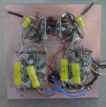
I fired the amp up at work with a couple of bench supplies, and no smoke. The 470 ohm cathode resistors on the 1625s look like they will need to go down to 330 ohms to get the 50ma of bias I'm looking for (total resistance 660 ohms). This is in conflict with the charts for the 807 in ultralinear mode I've seen on the net, but hey, you do what works. Bias on both sides, both stages is almost exactly the same, so the tubes are all fairly well matched, somewhat of a surprise.
The heat sinks on the MJE350s turned out to be a bit small - they are dissipating about 1.8W, and running 55-60C. This will need to change before I assemble the amp in a box. One possibility would be to bring down the current source a bit and increase the cathode resistor to simultaneously bring up the plate voltage and reduce the transistor dissipation, but I'll be throwing away gain, and I don't really want to use a split cathode resistor/ cathode bypass cap on the first stage if I can help it.
Not bad for an hour's work, all in all. Once I get the bias on the 1625s where I want it, the next step is to apply a signal and a load - I'm curious as to how much open loop gain I'll have.
Progress, progress...
I found that the plate voltage on the 6AH6s was too low, not allowing enough voltage swing to properly jazz the output stage. I replaced the 6AH6 input stage with triode conected 6AU6s, Which allowed me to push up the plate voltage on the input stage for better voltage swing. I also reduced the current source loads on the first stage from 10ma to 5ma. I'm able to get about 7-8W output into 10 ohms with very visible second harmonic distortion. Not too disturbing, as I'm still running open loop. With a 5k impedance output transformer (25:1 ratio), I'm not getting a whole lot of overall open loop gain (~12-13X), so something has to be done to boost the gain of the first stage to get some excess gain for feedback purposes. Tubelab's choice of a 12AT7 for the first stage of his Simple SE makes more and more sense....
I have two design choices that preserve the two 7-pin sockets on my input stage - use a pair of higher gain input tubes like the 6AB4 or 6AN4 (I nabbed a pair of 6AN4s today) or commit the ultimate heresy and go sand state at the input. This would involve using a PN4393 JFET input with a 6C4 cascode on top. At 5ma stage current, and 200Volt plate voltage, this gives me about 12V across the input JFET, which is a comfortable bias level. I'm tempted to do the sand state approach out of curiousity and sheer perversity, as I haven't seen it done for a power amp before.
The SMPS I designed for this amplifier is running nicely with resistive loads. Output voltages are pretty much spot on at 349V for the B+ and 12.6V for the filament supply. Initial efficiency measurement is about 86% at 110V input, which is not bad for a discrete ringing choke type of flyback supply. Next step is to let the supply soak in a bit at max dummy load (~52W) to check the component temperature rise.
I found out about the 6AB4 too when searching for a single triode alternative to the 12AT7. I have a few in my stash of used tubes that test out ok. They're ugly, but will work in a pinch. The 6AN4 is in the same family, but with a mu of 70 instead of 60. The 6AN4 is in the peanut-sized 6AK5-style envelope, so it'll look kind of funny sitting next to the 1625s. As I said previously though, I think I'll be trying the solid state cascode approach 'cause it's different, and it gives me a lot more open loop gain to play with ( the higher gain tubes would only give me about 2X more gain). I found some 6C4s in my stash that are electrically and cosmetically ok, and I already have a pair of JFETs picked out. I can always backtrack to the 6AN4 or 6AB4 if I don't like the results, as the rewiring needed is pretty minimal. Schematic will follow when everything is up and working.
The 6AN4 is in the peanut-sized 6AK5-style envelope, so it'll look kind of funny sitting next to the 1625s.
I recently finished a SimpleSE built on a polished diamond plate chassis. The 12AT7 looks rather wimpy standing next to those fat KT88EH's. Plenty of gain though, no problem driving any output tube into clipping in triode mode. A 6AN4 would be about the same height as the base on a 1625.
Attachments
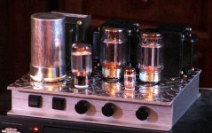
Nice amp. That 12AT7 looks like a little lost waif next to all the big boys. I took another look at your schematic and noticed that you were closing the loop around the output tube rather than the input. Can you expound? I've decided to shoot for higher overall loop gain to firm up the frequency response and improve the damping factor through feedback. The input stage looks like the one to massage, as the output stage has only 8X to 10X gain, depending on load. I currently have 10 ohm 10W resistors soldered across the transformer outputs, so the output stage gain is almost exactly 10x using the 1625s in ultralinear mode. BTW - the reason I used a 1625 rather than a beefier output tube was that I didn't want to go too far overboard with the SMPS design on the first pass. The 1625s are only running 15W dissipation apiece - with a nastier supply, I could no doubt kick them a bit harder without any ill effects.

- Status
- This old topic is closed. If you want to reopen this topic, contact a moderator using the "Report Post" button.
- Home
- Amplifiers
- Tubes / Valves
- "Shrine" SE Amp using 6AH6 and 1625