danFrank said:Hi,
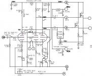
The Mark VI uses a 2200 ohm ct primary OPT.
The A451 is 2k2 a-a with U-L taps. The Mk.VI uses a 1k9 a-a OPT. It is near-trivial difference, perhaps one gage size up in the primary? I can find A451 coil wind design, but not taken a Mk.VI opt apart yet.
cheers,
Douglas
desperateaudio said:Sy,
One other question on this amp.
Plate is 500vdc
Screen at UL tap 500vdc
Grid -26
what is the ZERO SIGNAL current expected to be. I am having issues figuring it out.
Thanks
Hey Bandersnatch
Any answer to my question above. THX!!!
hey-Hey!!!,
To answer that, put a 1R resistor into the cathode circuit, and points to measure voltage developed across it. IIRC the 8417 has a 35 Watt plate rating, and at the top of the g2 voltage tolerance I'd want more like 25W into the tube...as in 50 mA/tube. 55 mA/tube is probably not dangerous, but I counsel conservatism at these operating conditions.
cheers,
Douglas
i have 10 ohms in line with each cathode so i know what they are getting now.
i was asking if anyone had an idea about what the original current was expected to be on the dynaco mk vi as it has in the orig design 500vdc plate and ul and -26vdc on grid. 8417 sheets show more then what you discuss by a good margin.
take a look at:
http://tdsl.duncanamps.com/dcigna/tubes/sheets/sylvania/syl-465h.gif
and
http://tdsl.duncanamps.com/dcigna/tubes/sheets/sylvania/syl-466h.gif
the second link shows 145ma for 2 tubes at -25vdc on grid and 445vdc plate/ul with a 3.5k load.
SY said:I think about 50-55mA per tube should be a good balance between distortion and lifetime, assuming you choose a good 6550 or KT88.
using 8417 as i have about 45 of them NOS or tested very good pulls. It is my experience that the current for the 6550/kt88 famliy is considerablly different from the 8417.
I am just wondering if anyone know what the ma would have been for the original amp? The manual does not say it just has expected voltage.
plate/ul = 500vdc
grid = - 26
load 1.9k
measurement at 30 ohm balance pot on output tubes in original circuit expected to be 1.8vdc
Ah, if you're using 8417, it's easy. The voltage across the cathode resistor in every Dynaco "fixed-bias" amp is 1.56V. Check that resistor's value, calculate current, and divide by four to get the per-tube idle.
My experience with 8417s in this and several other amps has not been good. Cherry plates at moderate dissipations and screen meltdowns are signatures of that tube.
My experience with 8417s in this and several other amps has not been good. Cherry plates at moderate dissipations and screen meltdowns are signatures of that tube.
SY said:Ah, if you're using 8417, it's easy. The voltage across the cathode resistor in every Dynaco "fixed-bias" amp is 1.56V. Check that resistor's value, calculate current, and divide by four to get the per-tube idle.
My experience with 8417s in this and several other amps has not been good. Cherry plates at moderate dissipations and screen meltdowns are signatures of that tube.
Use RCA and Sylvanias and have never had a meltdown yet. I also run them most often at 350vdc plate in triode mode and some times pentode with 300vdc on screen.
Thx for the info although on the mk vi the cathode is 1.87vdc not 1.56. The formula should work though.
Thx again
hey-Hey!!!,
I got the manual here:
http://www.tubes4hifi.com/downloads.htm
The cathode R is 7.8 Ohms, and with the traditional Dynaco-spec 1.56 volts across it we've got 50 mA/tube.
cheers,
Douglas
I got the manual here:
http://www.tubes4hifi.com/downloads.htm
The cathode R is 7.8 Ohms, and with the traditional Dynaco-spec 1.56 volts across it we've got 50 mA/tube.
cheers,
Douglas
Bandersnatch said:hey-Hey!!!,
I got the manual here:
http://www.tubes4hifi.com/downloads.htm
The cathode R is 7.8 Ohms, and with the traditional Dynaco-spec 1.56 volts across it we've got 50 mA/tube.
cheers,
Douglas
Thx,
See page 20 voltage at cathode is 1.87vdc therefore 60mA.
"7. This is mod suggested in Sound Practices. Apparently will reduce IM distortion, altho at cost of slightly lower power output.
A.Disconnect screen lead from pin 4 of output tube (8417,6550,or KT88,etc). Connect to pin 6. (assuming pin 6 is empty.
If not install a small terminal strip and connect screen lead to ungrounded lug.
B.Install 80V, 5watt zener diode between pin 6 (or terminal lug) and pin 4. Banded end (cathode) must be connected to
lead from transformer!"
The quote above is from Uncle Ned on the conversion of the Quick Silver amps from 8417's to 6550/KT88's.
The quote is specific to placing a zener in series with the UL taps for "IM Distortion". Altho I have seen this for different reasons such as having the zener cause a garanteed voltage reduction on the grid in respect to the plate. I think its called the "triode trick" but don't quote me.
Can anyone comment to this?
Hello,
Sorry to resurrect this old tread but I'm working on the same project. It seems, as suggested by SY, that a 12AX7 preamp/12AT7 phase splitter might be an option for this amp. (I have KT88's and a 12AU7/12AU7 LTP front end now.) Another option might be to use the Curcio 6922 cascode/6922 phase splitter designed for the Mark III as a front end.
Any thoughts?
Last edited:
I replaced the 7199 with the 12AU7/12AU7 front end to substitute. But that design was intended for 8417's. I was new to tubes then and was told to substitute KT88 all I had to do was change the cathode resistors and re bias. I have since learned that is not the case. When driven hard the front end distorts a bit. And I was hoping to clean that up. that is when I discovered the KT88's are less sensitive than 8417's.
I think the easiest thing to do is replace the 12AU7's with a 12AX7 and 12AT7. I have the 12AT7's already. It shouldn't take much to make the new tubes work. Also when I finished the front end the tubes didn't seem to draw enough current and I went down on the cathode resistors to get the current draw up. And haven't been back into the amps since.
I think the easiest thing to do is replace the 12AU7's with a 12AX7 and 12AT7. I have the 12AT7's already. It shouldn't take much to make the new tubes work. Also when I finished the front end the tubes didn't seem to draw enough current and I went down on the cathode resistors to get the current draw up. And haven't been back into the amps since.
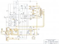
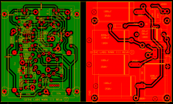
Compactron MrkIII PCB Design
I did the following design concept for someone per their expressed request and then they did not want it. Compactron tripple triode for a gain stage and then LTP with CCS and MosFet followers for screen drivers. I've used this topology on other amps with great success. I used all the design features that I've tried including plate-grid feedback aka Schade for the output tubes.
This PCB design has a power supply bypass PCB with bias voltages that piggybacks the main PCB to simplify the chassis wiring. Designed around parts available from Newark. 6AC10 or 6AK10 would be the best driver tubes.
Attachments
Last edited:
Hey Guys,
does anyone have a copy or a link for Kara Chaffee's article. I can't seem to find it.
Search for the March 2001 issue of AudioXpress. I was able to find a pdf online, but I don't have the link any more.
- Status
- Not open for further replies.
- Home
- Amplifiers
- Tubes / Valves
- Dynaco Mark VI