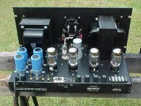
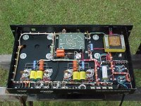
Well well, another serving of unmitigated hype from the ultimate master of it.  If you read the Q&As it gets even worse with meaningless math and now "gulp distortion".
Quote: "Another piece of great luck was that the amplifier had a power transformer connection for Japan line voltage and frequency. The voltage was for 100 volts @ 50 Hz. Now 100 / 50 = 2.00, and 120 / 60 = 2.00. That means that the volt-time product for the two cases cancel. We have 1.414 X .707 = 1. What could be better, and how fortunate. Viola', regulated screens and high voltage for the main B+! And the regulation is excellent - idle is 314 volt, full power is 308 volts = 98%". Two percent regulation is poor.
In my opinion this restoration is superior. Carver seems to have eschewed separate bias controls by keeping the original one-for-two scheme. And whether penthode operation over ultra linear sounds, or is, better is very, very debatable. Also, I have those Dynaco 451 output transformers and can tell you that they aren't that great. I have swept them at low power and their bandpass drops like a stone after 25KHz.
 If you read the Q&As it gets even worse with meaningless math and now "gulp distortion".
 Quote: "Another piece of great luck was that the amplifier had a power transformer connection for Japan line voltage and frequency. The voltage was for 100 volts @ 50 Hz. Now 100 / 50 = 2.00, and 120 / 60 = 2.00. That means that the volt-time product for the two cases cancel. We have 1.414 X .707 = 1. What could be better, and how fortunate. Viola', regulated screens and high voltage for the main B+! And the regulation is excellent - idle is 314 volt, full power is 308 volts = 98%". Two percent regulation is poor.
In my opinion this restoration is superior. Carver seems to have eschewed separate bias controls by keeping the original one-for-two scheme. And whether penthode operation over ultra linear sounds, or is, better is very, very debatable. Also, I have those Dynaco 451 output transformers and can tell you that they aren't that great. I have swept them at low power and their bandpass drops like a stone after 25KHz.

Attachments
 LVMan777 posting ads to the general forums is a violation of forum rules. Your posts have been removed. Please post to a SINGLE thread in Vendors. I recommend you read and adhere to the forum rules or your stay here will be brief.
http://www.diyaudio.com/forums/site-announcements/167561-diyaudio-rules.html
In particular rule 11 and Note 4.
There is a problem if you replace either 8417 or KT88 tubes; with 6550 tubes:
Fixed Bias (like this amp is?). Right?
KT88 maximum g1 resistor 220k for < 35Watt plate + screen dissipation,
100k for >/= 35 Watt plate + screen dissipation.
(fixed bias).
8417 maximum g1 resistor 100k (fixed bias).
6550 maximum g1 resistor 50k (fixed bias).
50k 6550 loads the 7199 circuit; more than 8417 100k, and more than KT88 220k / 100k.
"It is not nice to fool Mother Nature"
(do so at your own risk, Your Mileage May Vary)
'Nuf said.
Last edited:
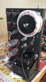
You could add a mosfet follower to drive the 6550. This will give you more swing as the 7199 now sees an easy load. In my case i used some beefy output tubes (in triode mode to match the transformer impedance) and a cathode follower driver (also output tubes) to drive the output tubes hard. Input is balanced cascode with current source. So the amp has a symmetrical input if so required. Local feedback loops only to keep the dc balance of the output tubes under full load.
Dynaco VI revisited
Some forty years ago I purchased three second hand Mark VI in a bad state.
I dismantled them, throw away the blown 8417 tubes (melted glass!) and redesigned a whole amp. New components apart from transformers.
I used 4 x 6550A (GE) with G1 resistors 270 K! Driver+input E88CC and 5687cascade as LTPairs(CCS: 2SK369V) and output tubes with cathode feedback from O/P transformer secondary. Bias 33 mA per tube. No global feedback! All supply voltages regulated apart from HV to output tubes.
These amps have given me great pleasure without any failure or problems. A couple of years ago I had to put new output tubes while the old GE ones couldn't any more. I put in one amp 4 chinese made 6550's and in another amp Russian 6550WE's without modifying anything in the circuits and just readjust the bias to all the output tubes. The amps have continued to work exactly as before with the GE tubes ( forty years ago I was able to purchase GE's - these are long gone now). I dug in my files and found the results of measurements :
124W output max (350V screen V) and superb frequency figures: 15Hz(-3dB)
from 25HZ to 50 kHz linear , 60 kHz -1dB and 80 kHz -3dB.
Would you mind sharing schematics ?Some forty years ago I purchased three second hand Mark VI in a bad state.
I dismantled them, throw away the blown 8417 tubes (melted glass!) and redesigned a whole amp. New components apart from transformers.
I used 4 x 6550A (GE) with G1 resistors 270 K! Driver+input E88CC and 5687cascade as LTPairs(CCS: 2SK369V) and output tubes with cathode feedback from O/P transformer secondary. Bias 33 mA per tube. No global feedback! All supply voltages regulated apart from HV to output tubes.
These amps have given me great pleasure without any failure or problems. A couple of years ago I had to put new output tubes while the old GE ones couldn't any more. I put in one amp 4 chinese made 6550's and in another amp Russian 6550WE's without modifying anything in the circuits and just readjust the bias to all the output tubes. The amps have continued to work exactly as before with the GE tubes ( forty years ago I was able to purchase GE's - these are long gone now). I dug in my files and found the results of measurements :
124W output max (350V screen V) and superb frequency figures: 15Hz(-3dB)
from 25HZ to 50 kHz linear , 60 kHz -1dB and 80 kHz -3dB.
Well well, another serving of unmitigated hype from the ultimate master of it. :soupir: If you read the Q&As it gets even worse with meaningless math and now "gulp distortion".
Quote: "Another piece of great luck was that the amplifier had a power transformer connection for Japan line voltage and frequency. The voltage was for 100 volts @ 50 Hz. Now 100 / 50 = 2.00, and 120 / 60 = 2.00. That means that the volt-time product for the two cases cancel. We have 1.414 X .707 = 1. What could be better, and how fortunate. Viola', regulated screens and high voltage for the main B+! And the regulation is excellent - idle is 314 volt, full power is 308 volts = 98%". Two percent regulation is poor.
A mon avis cette restauration est supérieure. Carver semble avoir évité les contrôles de biais séparés en conservant le schéma original un pour deux. Et qu'il s'agisse d'un fonctionnement en penthode sur des sons ultra linéaires, ou mieux, c'est très, très discutable. De plus, j'ai ces transformateurs de sortie Dynaco 451 et je peux vous dire qu'ils ne sont pas si géniaux. Je les ai balayés à faible puissance et leur bande passante chute comme une pierre après 25KHz.:non:
@Soulimani This is an English language forum, please post in English. Use a translator if necessary.
Ceci est un forum en anglais, merci de poster en anglais. Utilisez un traducteur si nécessaire.
A mon avis cette restauration est supérieure. Carver semble avoir évité les contrôles de biais séparés en conservant le schéma original un pour deux. Et qu'il s'agisse d'un fonctionnement en penthode sur des sons ultra linéaires, ou mieux, c'est très, très discutable. De plus, j'ai ces transformateurs de sortie Dynaco 451 et je peux vous dire qu'ils ne sont pas si géniaux. Je les ai balayés à faible puissance et leur bande passante chute comme une pierre après 25KHz.:non:
In my opinion this restoration is superior. Carver appears to have avoided separate bias controls by retaining the original one-for-two scheme. And whether it's penthode operation on ultra-linear sounds, or better, is very, very debatable. Also, I have these Dynaco 451 output transformers and I can tell you they're not that great. I swept them at low power and their bandwidth drops like a stone after 25KHz.

- Status
- Not open for further replies.
- Home
- Amplifiers
- Tubes / Valves
- Dynaco Mark VI


