The think that the 6GK5 is a good choice for CF duty too. (It is also a good candidate for phono stages). In my view, the main two small-signal requirements for a CF tube, derived from examining the gain equations, are high mu and high gm. Mu needs to be high to keep gain close to one (which then reduces distortion when mu varies with signal swing). High gm means that the output Z (which is actually rp/mu+1 ~ rp/mu = 1/gm) will be low. Besides the usual driving advantages of a low output Z, it also helps to reduce distortion by keeping the gain closer to one, or said another way: the effect of the non-linearity of 1/gm in the output voltage divider relationship is reduced when gm is large. The 6GK5 is gifted with high mu and high gm (as well as a partially screened plate to grid which lowers Cgp). However, I would not characterize this “gain controlled VHF triode” as being particularly linear (say, compared to a garden variety 6DJ8). Look at the curves in the GE data sheet. Mu falls at lower currents, although this can be mitigated by using high resistance loadlines. It’s better than its cousin the 6ER5. Not a problem in the CF, the 100% feedback reduces distortion anyway, and not a problem in the first stage of a phono stage where signal levels are so low.
You may need a small series output resistor (a cathode stopper) with these potent VHF tubes if the loading is capacitive, since feedback through Cgk can create instability when the load is reactive. Also make sure to bypass the plate with a small short-leaded poly cap to ground. Otherwise, at VHF the plate can make gain against the stray reactances it sees.
You may need a small series output resistor (a cathode stopper) with these potent VHF tubes if the loading is capacitive, since feedback through Cgk can create instability when the load is reactive. Also make sure to bypass the plate with a small short-leaded poly cap to ground. Otherwise, at VHF the plate can make gain against the stray reactances it sees.
Brian Beck said:The think that the 6GK5 is a good choice for CF duty too. (It is also a good candidate for phono stages). In my view, the main two small-signal requirements for a CF tube, derived from examining the gain equations, are high mu and high gm. Mu needs to be high to keep gain close to one (which then reduces distortion when mu varies with signal swing). High gm means that the output Z (which is actually rp/mu+1 ~ rp/mu = 1/gm) will be low. Besides the usual driving advantages of a low output Z, it also helps to reduce distortion by keeping the gain closer to one, or said another way: the effect of the non-linearity of 1/gm in the output voltage divider relationship is reduced when gm is large. The 6GK5 is gifted with high mu and high gm (as well as a partially screened plate to grid which lowers Cgp). However, I would not characterize this “gain controlled VHF triode” as being particularly linear (say, compared to a garden variety 6DJ8). Look at the curves in the GE data sheet. Mu falls at lower currents, although this can be mitigated by using high resistance loadlines. It’s better than its cousin the 6ER5. Not a problem in the CF, the 100% feedback reduces distortion anyway, and not a problem in the first stage of a phono stage where signal levels are so low.
You may need a small series output resistor (a cathode stopper) with these potent VHF tubes if the loading is capacitive, since feedback through Cgk can create instability when the load is reactive. Also make sure to bypass the plate with a small short-leaded poly cap to ground. Otherwise, at VHF the plate can make gain against the stray reactances it sees.
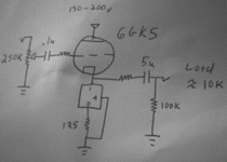
Thanx for the great info. Yeah, looking at the 6gk5 sheet, I liked what I saw... except for a strange bunching of the curves, which is the reason that I didn't just jump on that tube without hesitation. I think I'll run it around 10mA with 150-200v on the plates and plunk a LM317 in the cathode as a CCS ( since I am out of BJTs and decent JFETs at the moment)and then see where I stand:
Attachments
You'll see that bunching of the plate-characteristic curves in a lot of RF tubes as an intentional design feature. Similar effects are referred to by various names such as gain-controlled, variable-mu, and remote cut-off. The bunching is not there just to annoy us audiophiles, but to allow for varying the gain by varying the grid bias, for AGC control and sometimes for modulation. Usually this is accomplished by varying the pitch or spacing of the grid wire as it is wound, creating regions with different effective mu contributions. This effect creates mostly second and even order harmonic distortion that would be cancelled in a push-pull or diff amp using these tubes. Also, much of the mu variability is vanquished with high plate loads, a CCS or a choke load.
Still, Santa, please send me a pair of 6GK5s with the even plate curve spacing of a 300B for Christmas.
Still, Santa, please send me a pair of 6GK5s with the even plate curve spacing of a 300B for Christmas.
Aletheian,
On your proposed schematic: With the plate current and voltage you’ve picked, the cathode voltage will only be about +1.5V. That’s not enough to allow the LM317 CCS to work, all the more so when the input voltage swings low. It’s best to use a low negative voltage DC supply to which to connect the south end of the CCS. One option, if you use a DC heater supply, is to connect the positive end of that floating DC supply to ground, giving you -6.3V to play with, and even that is only marginal. -12.6 V would be better (series tube heaters perhaps?) In any case, the LM317 CCS will cease to behave as a good CCS at higher frequencies in the audio band, so cascoding is a good idea to keep the effective impedance of the CCS high as seen by the cathode. A CCS used for CF duty is less critical than a plate loading CCS by a factor of mu+1, but still…
You’ll also need some DC ground reference for the grid. A meg from grid to ground ought to do.
Brian Beck said:Aletheian,
On your proposed schematic: With the plate current and voltage you’ve picked, the cathode voltage will only be about +1.5V. That’s not enough to allow the LM317 CCS to work, all the more so when the input voltage swings low. It’s best to use a low negative voltage DC supply to which to connect the south end of the CCS. One option, if you use a DC heater supply, is to connect the positive end of that floating DC supply to ground, giving you -6.3V to play with, and even that is only marginal. -12.6 V would be better (series tube heaters perhaps?) In any case, the LM317 CCS will cease to behave as a good CCS at higher frequencies in the audio band, so cascoding is a good idea to keep the effective impedance of the CCS high as seen by the cathode. A CCS used for CF duty is less critical than a plate loading CCS by a factor of mu+1, but still…
You’ll also need some DC ground reference for the grid. A meg from grid to ground ought to do.
CRAP! I forgot to draw in the 1Meg grid resistor... good catch. i meant to draw it up between the cap and the grid stopper.
For some reason i thought that the cathode coltage would have been higher than 1.5v, I guess I should have run the numbers first. in that case, you are correct, I'll need a -ve voltage reference. I was planning to regulate a 12v tap down to 6.3v DC for the heaters, but maybe I'll run AC heaters and then rectify the voltage after the filament to make a suitable reference.
I had assumed a higher bias point, but since the cathode voltage is so low, is there a chance of clipping with a hot signal? Should I go with another topology? Cascoding would give me way too much gain to deal with, and I'd hate to add components just to dump volts that I didn't need in the first place.
aletheian said:I think I'll run it around 10mA with 150-200v on the plates and plunk a LM317 in the cathode as a CCS ( since I am out of BJTs and decent JFETs at the moment)and then see where I stand:
Got any 6AU6s in your stash? Pentodes are great as CCS loads underneath a triode CF. Rig the main PSU up bipolar and stop worrying about a "hot" I/P signal.
aletheian said:I had assumed a higher bias point, but since the cathode voltage is so low, is there a chance of clipping with a hot signal?
Yep, unless you extend the cathode swing range with a negative supply. Eli makes a good suggestion. In fact a cascoded CCS with a pentode on top is probably about the best you can do.
They do a pretty good job in the tail of an LTP splitter as well.Pentodes are great as CCS loads underneath a triode CF.
Eli Duttman said:
Got any 6AU6s in your stash? Pentodes are great as CCS loads underneath a triode CF. Rig the main PSU up bipolar and stop worrying about a "hot" I/P signal.
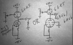
I think I have enough 6au6 to use as currency for a small nation. Also EF184 as well as 6bh6/6661. So a pentode CCS in the cathode of a 6gk5 set for 10mA with a bipolar 85v+/85v- supply. I had only planned on 300mA or so of filaments to feed, but i could dig around for a more robust tranny.
How about more hearasy with a high voltage mosfet in the cathode and a bipolar supply?
Attachments
- Status
- This old topic is closed. If you want to reopen this topic, contact a moderator using the "Report Post" button.
- Home
- Amplifiers
- Tubes / Valves
- Unity buffer from 7-pin triode?

