I have a batch of these tubes (from an organ) and I'm trying to figure out what to do with them. The problem is that the cathode is shared between the triode and pentode sections.
http://tdsl.duncanamps.com/show.php?des=6X8
Any ideas for a useful application?
-- josé k.
http://tdsl.duncanamps.com/show.php?des=6X8
Any ideas for a useful application?
-- josé k.

here is thread started by ray_moth: http://www.diyaudio.com/forums/tubes-valves/140028-radford-pentode-triode-ltp-splitter.html
Last edited:
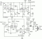
Look here for a nice ideea:
Apologies for being OT, but this picture is very interesting ! I have been contemplating something like this with my extra TV tubes (2x PCF80 + 2x PCL805 for single channel class-D PP stage).
My plan was 2x triode (current source & switch feeding/draining a capacitor) as triangle wave generator, driven in a loop by 2x triode (schmitt trigger operating the switch), PWM and input fed into 2x pentode (LTP comparator), driving power pentode pair (PP output) to full extremes. It would take approximately 20Vpp swing on the grids of output tubes to drive them into cut-off which should be doable.
This was supposed to be bass/sub channel but I have only modelled its JFET version in LTspice, I have yet to find enough time and determination to go for tube version (my assumption was many different supply voltages would be needed, which is a big deterrent).
The picture you posted looks simpler but I'm not quite sure about the oscillator's distortion (nonlinearity)

The picture you posted looks simpler but I'm not quite sure about the oscillator's distortion (nonlinearity)
Here's the web page that describes that project in detail: Clicky. The oscillator isn't all that linear, but then, again, it is quite simple, and so technical compromises are made here.
Class D is hella useful for RF, or audio where you need to pack lotsawatts in small packages, though I'm not too sure how "HiFi" it really is. All you can do here is give it a go and see how it performs. Sometimes, you never learn unless you try.
(Had that same problem when contemplating using a cascoded LTP: nothing I could find on the sonics of the hollow state cascode, so I just went ahead and did it. It worked great.)
Look here for a nice ideea:
Class D tube amp...
The oscillator isn't all that linear, but then, again, it is quite simple, and so technical compromises are made here.
I thought so, the waveform looks ungodly nonlinear in those pictures
My idea will (well, hopefully
) use same number of tube devices (7 for SE just as this one, 8 for PP which is most convenient for 2x PCF80 + 2x PCL805 or PCL84) but will employ a different design, alas with no room for common cathode dissimilar tubes (and no sand, of course), hence off-topic; moderator should split this topic if we had veered to far This is what I'm thinking:
CCS + switch should provide almost perfectly linear triangular wevaeform on both flanks (delinearized only by grid impedance of both following stages, in combined range of say 1M for both together). With low enough a switching frequency (for bass amplifier this should be fairly low, say 10 KHz, instead of 200 KHz for a full range amplifier) and high enough a current provided by the CCS I should end up with relatively large capacitor, offsetting delinearisation as much as possible - the larger the cap and current, the less pronounced the effect of loading on it will be (without the use of extra buffer stage).
Schmitt trigger will provide sharp switching and its hysteresis will set the range of triangle waveform levels (the higher the hysteresis, the larger the triangle wave amplitude). So in essence hysteresis adjustment pot will serve as the volume control.
I count on pentodes to deliver as much voltage swing as possible in comparator. This is the weak point of my idea in my opinion but I'm counting on output filtering to offset it to some extent and on pentodes do do as much voltage gain as possible (in order to drive grids of the power tubes into both extremes). This is why I was enquiring in this forum about identical low signal pentodes in same envelope the other day, but Russian 6R5P (the only match for set requirements) appears to be made of unobtainium ...
Since I have considerably less time than I have ideas to fill it with I haven't even gotten around to calculating required resistor values (= key for operation of the triangle generation stage, otherwise it won't oscillate) but that pic reminded me of my idea once again
Last edited:
I thought so, the waveform looks ungodly nonlinear in those pictures
That's the big problem: trying to get a good triangle wave from a passive integrator. It's trivially easy with solid state, since op-amps include balanced, complimentary followers that can source and sink currents equally. Kinda hard to do without being able to use a "P-Channel" VT.
If you're trying to design a hollow state Class D amp, you have a good deal more latitude, since the schemo you reference was for a contest for using as many of these dissimilar duals as possible. If you can choose any VTs, you can pick your particular topology without that constraint.
There might be some inspiration in the old Tektronix tube ramp generator designs, although they do generate a sawtooth. You can dc offset the audio signal to compensate. These are actually quite linear.
Take a look here: http://www.leftfield.org/~dd/TE/TekConcepts/062-1098-00_sweepCkts_Jun69.pdf
Based on the desire for a simple low order LPF (integrating filter) at the output of the amplifier you might want a PWM frequency in the range of 100kHz or so..
Look here for some generally applicable guidelines, note that they use a first order filter/integrator though: http://ww1.microchip.com/downloads/en/AppNotes/00538c.pdf Note that the 2nd order filter shown in the design posted is a considerable improvement. (Note also that the equations shown in the app note should be revised for an LC filter.)
Last edited:
That's the big problem: trying to get a good triangle wave from a passive integrator. It's trivially easy with solid state, since op-amps include balanced, complimentary followers that can source and sink currents equally. Kinda hard to do without being able to use a "P-Channel" VT.
I've been thinking about this before and I realized all I really want are flat slopes; it doesn't really matter whether there is (a slight) imbalance in absolute slant between ascending and descending side of the waveform, as long as they are as linear as possible. Imbalance means there are two chopping frequencies, but in the end it is the duty cycle that matters, as long as output filter can cope with both frequencies (= they are not to far apart), right ? Since schmitt trigger dictates the voltage swing, it will always keep the ramp between two values, regardless of the slope.
After I got it working I have deliberately simulated very unbalanced JFET implementation (N channel only, since I haven't quite figured out how to use tube models in LTspice yet I was using those as tube substitutes - I'm a bit on the thick side when it comes to LTspice
) and it was operating as predicted.Fixed current source (one triode) feeds integrator capacitor from its cathode with current I. Voltage controlled current source (another triode) drains it with approximately 2I when conducting, and doesn't draw current when cut off. In reality there might still be some current drain but this is merely a matter of adding this constant drain to the calculations to keep the 1 : 2 ratio of both currents or somewhere thereabouts in order for chopping frequencies to be as close to one another as possible. As long as second current source can be controlled in a manner to keep its current constant, the ramp will be as linear as possible without some sort of compensation.
Since only a couple of volts swing would be required of the triangle wave generator (enough to match full amplitude of input signal and no more, to keep the gain up), this doesn't seem all that unrealistic, especially compared to the waveform showing in that picture
This is operation on a fraction of the B+ that both CCS valves could swing.Another plus of deliberate triangle wave implementation is that there is no "deadtime" that any sawtooth oscillator will experience when returning to initial state. This is basically "the other slope" of the triangle wave, one that will be much higher in frequency and can cause all sorts of nastiness at the filter/output. My version strives to keep both slopes matched as close as possible without going to extremes (matching them perfectly would be a waste of time).
Incidentally I too was planning to use combined triode+pentode TV valves for the first version because that's what I have lying here, doing nothing
It would result in an ugly mess of connections because different sections of same tube would be used in different parts of the circuit. Circuit could be simplified considerably as far as connections between various sections go with the use of symmetrical dual valves.I would think that symmetrical slopes if you use a triangle wave generator would be rather important from the standpoint of distortion? (A change in slope would imply a duty cycle change and an amplitude mismatch between the rising and falling edges of the waveform being sampled..IMO) This is one area where level shifting the audio waveform so that a sawtooth could be used makes some sense to me..
No, think about it - input signal is chopped into duty cycle ratio based on slope and output device doesn't care about PWM frequency (as long as it is within some sane interval), all it cares about is the duty cycle.
Assuming input signal is at same 50% level through two consecutive halfperiods of the triangle wave (a simple example to illustrate the point), it will be converted into 50% PWM duty cycle during both halfperiods (PWM frequency being twice that of the oscillator), regardless of the slope of the triangle wave.
If slope of both halfperiods is different, each will result in different PWM frequency but same duty cycle. As long as frequencies aren't horribly mismatched, the output filter should have no trouble dealing with them and whatever mismatch there is, it will result in some DC offset (lower frequency output being dampened slightly less than that of higher frequency).
Hmm ... could this side effect be used to steer the "fixed" CCS to eliminate any DC offset ? I'll have to think it through, it hasn't occured to me before. I was counting on eliminating imbalance by tweaking cathode bias of output tubes.
Me ? I decided to try to implement it using protoboard and JFETs (= "heaterless triodes") first, schmitt trigger (the crucial part I wasn't very sure about) seems to be working at LF, haven't tested it at ultrasonic frequencies yet, I haven't had time to put together more mundane bits, namely the CCS + VC CCS and LTP comparator.
I did realize something that wasn't apparent from LTspice though: it seems to be easier to control the upper CCS rather than the lower one as DC coupling is required between schmitt trigger and VC CCS and the fact that the schmitt trigger output swings (roughly) between B+ of second device in ST and its drain/cathode potential. The principle of operation would remain the same, the controlled CCS sources twice the current fixed CCS sinks.
If you feel like experimenting, I can cobble together the schematic which is currently only in my head and you can determine timing component values experimentally. The key part is to get the schmitt trigger working, the rest should be relatively easy, at least for bass audio frequencies which is where this thing was intended to operate at (with PWM frequency in lower ultrasonic range).
- Status
- This old topic is closed. If you want to reopen this topic, contact a moderator using the "Report Post" button.
- Home
- Amplifiers
- Tubes / Valves
- Usefulness of 6X8 tube?