Interesting point Sy, although I've never found that to be particularly true. But for the sake of the conversation, if it were (or is) true, theoretically, the capacitive feedback loop from the screen tap can't address the issue you raise any better than the main NFB loop can. In the real world however, where transformers can and do have different response characteristics on different windings and taps, I suppose the screen tap loop could be more effective in dealing with the issue. But since all windings produce a composite output of the push-pull signal, the idea that feedback taken from only one output tube of a push-pull design corrects only issues on that side of the push-pull circuit seems quite implausible in this case, given that the loop in question is returned to the same input that the main NFB loop is returned to. In my experience with this design, I have found that the capacitive loop acts to tailor the response of the active amplification circuits first, so that the main NFB loop applied around the active elements and the OPT remains stable under a wide range of possible loading conditions. Hafler was at the forefront of the whole NFB stability issue, which peaked about the time his original MK II amplifier was introduced in 1955. The all too typical Williamson offerings of the day were infamous for breathing woofers and blown tweeters, where as the Dynaco design (at the time) represented a real advancement in stability in FB amplifiers over the more traditional offerings that were available. It is my experience that his approach to tailoring the response of the basic gain model before application of GNFB, in addition to the wide response his transformers offered, contributed significantly to his success in this area. Others may have different experiences regarding this, so I appreciate any and all input offered.
Dave
Dave
The idea is to balance the open loop frequency response for both polarities before applying the overall loop. The cap doesn't work perfectly, but it does work. Pull the cap out of any of the Dyna amps (this was a trick they used in almost anything they made). In some cases, the amp will still work fine, but in many others, you'll see ringing on one side of square waves. In some, you'll get bursts of oscillation, especially when driving speakers.
Absolutely agree -- although I've found that simplying adjusting the components of the typical transitional phase shift network so often seen connected to the plate of an input tube will also allow you to either eliminate the ring, produce exaggerated ring on both sides of a square wave, or shove it all to the top or bottom of the wave. I have always found these effects to be from an overall response that was not tailored appropriately (appropriate tailoring always resolves them) -- regardless of the type phase inverter used -- rather than being due to significantly different response on one side. I appreciate your input. It give me more to investigate!
Dave
Dave
Pixworld -- Thanks for the kind words about my EFB modification.
Where can one find out more?
dave
Dave -- You can read my article introducing the EFB modification here:
http://www.tronola.com/A_New_Look_At_An_Old_Friend.pdf
It is posted in the Dave's Lab portion of the Tronola site which is operated by my good friend Steve Lafferty. He also has numerous other articles and modifications posted there you might find interesting.
Thanks for the interest!
Dave
http://www.tronola.com/A_New_Look_At_An_Old_Friend.pdf
It is posted in the Dave's Lab portion of the Tronola site which is operated by my good friend Steve Lafferty. He also has numerous other articles and modifications posted there you might find interesting.
Thanks for the interest!
Dave
mr2racer:
Here's a post on another forum describing how to implement the PAS phono on the SCA35 board. supposedly better. You should be able to bypass the selector switch mounted components completely, if you eliminate tape head equalization. I'm not a big fan of the pas though, I'd put a RCA phono circuit with buffer, or Koren phono (haven't heard that one) if I was doing it.
Dynaco-Doctor Forum: SCA-35 Phono Board Modification by Flyquail56
JGF,
Thank you, that is EXACTLY what I was looking for! I've heard Joe's upgraded PAS and for this project I think its fine. (For myself I'm waiting for SY's design.) I looked at converting this board to a PAS since its layout is the same except for the tape head. But I wasn't sure about what to do with those tape head lug connections on the board.
But still I have a question. I did away with the Dyncao selector switch entirely so none of the connections are still there. The instructions say to replace R11 with a jumper and connect, as in the original, the phono input to lug #6. Which, I assume, is connected to lug #8 via the selector switch. Wouldn't it be easier to connect the phono input directly to lug #8 like the PAS. And only connect the output from lug #11 to the selector switch?
Kevin
Last edited:
Kevin,
I haven't done this mod on the SCA35, only worked on the PAS. I wouldn't want to try to reverse engineer those switch connections... If you want to put a pas phono circuit in, I think your best bet is to draw up that schematic, then work it into the SCA phono board. Yes, if you're only using mag. phono, the rca jack input should go directly to the board, the phono circuit's only connections to the selector switch will be its outputs.
Good luck!
John
JGF,
As I was writing the last post I realized I had figured it out. I think what they were trying to do was keep the changes to a minimum. But there schematic means two connections for phono on the selector switch. If the input is connected to #6 it has to arrive at #8 eventually. That much I know. And the output is from #11. The rest of the connections are accounted for. In fact I think a better way to do it is a direct input to the board at #8. Then instead of replacing R-11 with a jumper I can put the first half of the feedback network there. Then connect #7 to #3 and put the second half of the feedback in place of the jumper for R-9. And Then I can leave the coupling cap on the board where it belongs.
Kevin
Hey All.
I've seen several ways of installing volume controls. In this case the SCA and the PAS have a 250k volume pot. At this point the phono preamp output is connected to the first position on the selector switch. The other four line level inputs are connected to the selector switch also. It seems the output from the selector switch should attach to one end of the pot. The wiper to the output to the 12DW7 on the ST35 board. And the opposite end to ground. The question I have is do I need anything between the shunt end of the pot and ground? There isn't anything in this position on the SCA. But the signal runs from the wiper volume through the PEC 555002. Can I go straight from the wiper to the .1uf cap at the input of the output section?
Kevin
Replace the electrolytic capacitors and the tubes. The coupling caps would also be something I'd go after. Don't use fashion parts, normal polypropylene caps (e.g., Wima MKP or 715P Orange Drops) will be fine in this circuit. Clean the switches and potentiometers with spray contact cleaner and some rotation. Then sit back and enjoy.
After you've got it refurbished and used it for a while, we can talk about upgrades.
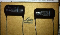
Do you have any info. for this capacitor? I bought them from Ebay several years ago but I don't know about them.
Attachments
tofsound,
CDE is Cornell Dublier Electronics. Probably not a bad cap but I don't think its anything special either. Personally, I like Solen polypropylene caps. Which in that value cost about $3 a pair. So why would you want to risk using a cap of unknown quality and unknown age to save $3? Once you get past the real expense of transformers and to some extent tubes, the little bits are cheap. I agree with SY. You don't need to buy 'boutique caps.'
For example, I buy my caps from Tube Depot in Memphis. A .1uf @ 630 volt Solen metalized polypropylene is $1.45. That's peanuts even for me. An Auricap .1uf 450 volt is $11.85 from Tube Depot. In your average push pull power amp you'll need six coupling caps. That's $8.70 for Solens but $71.10 for Auricaps for an amp. Wima, Panasonic, and Orange Drops are about the same price as the Solen's.
My point is those caps could be twenty years old. As A.J Foyt says buy something "where you know where it come from". And how long its been on the road.
Thanks for your advice.tofsound,
CDE is Cornell Dublier Electronics. Probably not a bad cap but I don't think its anything special either. Personally, I like Solen polypropylene caps. Which in that value cost about $3 a pair. So why would you want to risk using a cap of unknown quality and unknown age to save $3? Once you get past the real expense of transformers and to some extent tubes, the little bits are cheap. I agree with SY. You don't need to buy 'boutique caps.'
For example, I buy my caps from Tube Depot in Memphis. A .1uf @ 630 volt Solen metalized polypropylene is $1.45. That's peanuts even for me. An Auricap .1uf 450 volt is $11.85 from Tube Depot. In your average push pull power amp you'll need six coupling caps. That's $8.70 for Solens but $71.10 for Auricaps for an amp. Wima, Panasonic, and Orange Drops are about the same price as the Solen's.
My point is those caps could be twenty years old. As A.J Foyt says buy something "where you know where it come from". And how long its been on the road.
I bought this capacitor at a value little it more than Solen. I can't exactly remember but the ebay seller told me that this is a good cap. Anyway I have 4 0.47uf/600vdc solen caps so I can use them later. I did not feel much differences with changing caps but did with bypassing tone control.
Anyone,
Both the SCA and the ST use a 50 ohm 5w first resistor. On the ST the second resistor is a 6.8k to get the right voltage for the 7247. But the SCA uses 2.2k for the 7199. In the SCA it is followed by another 2.2k and a 22k that supplies the phono board. Since resistors are linear, if I use the 6.8k for R40 on the SCA instead of 2.2k, followed by the second 2.2k would it make sense to subtract the difference for the last resistor? I.E. 22,000 - (6800 - 2200) = 17,400. So, 17.4k for the last resistor before the phono board? Is it that easy?
Kevin
After some modification(replacing Cap board, adopting EFB) I had square wave test with signal generator and oscilloscope.
The test wasn't precise but maximum output was around 16 watt with 7 ohm dummy load (it starts clipping from the output of 30v peak to peak). The output bias current was 27mA each. The interest thing is that outputs of phase spliter are not same. While the upper output(in the schematic) is something relatively modest the lower one is somewhat ugly. Here are the screen shots. I don't know why both are different. Maybe it's because the lower output related to feedback loop ??
The test wasn't precise but maximum output was around 16 watt with 7 ohm dummy load (it starts clipping from the output of 30v peak to peak). The output bias current was 27mA each. The interest thing is that outputs of phase spliter are not same. While the upper output(in the schematic) is something relatively modest the lower one is somewhat ugly. Here are the screen shots. I don't know why both are different. Maybe it's because the lower output related to feedback loop ??
Attachments
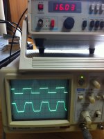
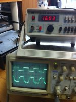
tofsound -- having a different signal appear at each output tube grid in a feedback amplifier with it driven to full power output is not uncommon. In fact, it is more common than not, depending on the frequency and output level used, as well as the overall design of the amplifier. The technique used to achieve proper HF stability also has a hand in this effect. Since the composite waveform achieved from the OP transformer secondary is the main goal, the individual drive waveforms are of little concern unless they are unequal in amplitude, or show parasitic oscillations.
With the stock power transformer operating from a capable 120 vac power source and fresh output tubes, the unit is capable of 17.5 watts RMS from each channel with both channels driven into 8 ohms when the EFB modification is installed. In your case, with the lower load impedance you were using for your measurements, 16 watts would seem about right. Use of the EFB modification has no bearing on the waveforms you observed at the output tube grids, as these waveforms will have the same appearance even with the original bias scheme in place under the same measurement conditions.
Dave
- Status
- This old topic is closed. If you want to reopen this topic, contact a moderator using the "Report Post" button.
- Home
- Amplifiers
- Tubes / Valves
- SCA-35 Dynaco