mr2racer:
I have a 32.1k feedback resistor in there now, on the 16 ohm tap. Same size cap across it.
I may lower it just a little more (maybe I'll try 29 or 30k) I'm getting just a hint
of upper midrange harshness on horns and lead guitar sometimes, which was not
there with the original feedback resistor value.
Power supply filtering has been increased also.
Last edited:
Racer -- Since the NFB level is reasonably similar between the ST and SCA designs, you can't just look at the value of the FB resistor and determine from that if one design has more operating gain than another -- or conversely, more feedback than another. Rather, it is all dependent on the amount of open loop gain (OLG) of the stages that the feedback is placed around, and the level of FB voltage returned to the input as determined by the speaker tap used and the ratio of the resistors used in the feedback network.
In the case at hand, the extra gain largely comes from using a pentode input stage in the SCA (which easily provides about 5X the gain of the triode input stage of the ST), and from only a slight reduction in the effective FB level in the SCA design.
The FB network of the SCA design only applies about 13.5% of the FB voltage around the power amplifier section that the ST design does. But with the added gain of the pentode input stage within the FB loop, the effective FB level of the SCA design is still about 70% of that used in the ST design. Since it is not 100%, that slight reduction in FB level, coupled with the 5X gain increase provided by the pentode input stage reduces the 1.0 vac sensitivity level of the ST design, down to about .15 vac for that of the SCA amplifier board. Of course, in the SCA design, the gain advantage is put to good use by allowing the installation of losser type tone controls ahead of the amplifier proper, so that the effective operating sensitivity of the two amplifiers (with the SCA tone controls set flat) is basically the same.
I hope this helps with your project!
Dave
")
Thanks for the help guys. I was counting on the standard 2 volt output common with a CD player to make up for the loss in gain. The question is will that doubling of input overdrive the 12AX7 half of the 12DW7? And as mentioned earlier in the thread. Might it be better to use a 12AX7 instead of the 12DW7? What changes would be necessary to the ST boards to make that work? Other than cathode resistors?
No problem with overdrive with just disc player -> volume control before the 7247/12dw7. That's exactly what I've been running for a while. I'm not a huge
fan of the 12au7 either, but it sounds ok in this circuit. 12ax7 in the splitter position is very iffy, you can't run much current through it. That 6n1p circuit and Morgan Jones' 6dj8 circuit are the only ones I've seen fully worked out that might sub given easy power supply mods if you really wanted to get rid of the 7247.
I suppose a 12at7 could be made to work there, but just dropping it in to the existing circuit could well be worse..
Right, until you mentioned it I assumed they used the 12AU7 as the phase splitter and the 12AX7 as the gain stage. In the Dynaco catalog there is an EL-84 amp that uses a single 12AX7 as a combination gain/phase splitter. I can only assume that the 12AX7 has sufficient amperage output to drive the EL-84's. And the position of the tubes has more to do with matching impedance's than anything else.
Chris --
I tried removing the positive feedback, but liked it better with. I guess they optimized everything around that.
mr2racer--
I've only seen schemos of amps with both halves of the 12ax7 making up the splitter driving el84s, but not a concertina. Also, if I read the theory right,
gain would be lower using a pair type splitter, and it seems just about right, if not
just a bit low as is (without a preamp).
Racer -- the positive FB loop has nothing to do with the balance of the concertina, but everything to do with making the effective gain of the first stage as high as possible. Remember, the higher we can make it, the lower the input driving requirement will be for a given FB level. In trying to shoot for a 20 db FB factor, and an input sensitivity of 1.0 vac, the positive FB loop helped to create enough gain within the loop to achieve those figures.
Dave
Dave
Hey All,
I found some 6P15P tubes online from a Russian retailer and bought 17 of them. I was under the impression that they were identical to an EL84 but now find that to be untrue.
I plan on using them in a Dynaco SCA-35 I'm building. I'm substituting ST-35 boards to swap the 7199 for the 12DW7 preamp/phase splitter. And removing everything but the volume control from the circuit.
Obviously, on the EL84 the suppressor (?) grid is internally connected to the cathode on pin 3. The 6P15P does not have this connection. If my tired old eyes aren't failing me the suppressor grid on 6P15P is connected to pins 1&6. The ST-35 manual voltage chart lists 13.5 volts on pin 3 and 0 volts on pins 1&6. This is important because of the 150 volt limit on the suppressor grid for the 6P15P.
I also found the "Hazen" mod for Decware amps where the EL-84 cathode and suppressor grid are connected by a non-polarized film cap. Since there is an internal connection for these I'm assuming the cap is a bypass cap?
So these are my questions. Is the 150 volt limit on the grid for a pentode amp where the grid is driven? This not the case in the ST-35 as it is an ultra-linear amp. Second, should I connect the cathode to the suppressor grid? Third, Does anyone know the value of that cap? And lastly, could I damage my new amp by experimenting with this connection either by cap or by a wire?
Since the ST-35 boards use a chassis mount socket for the EL-84 rewiring the output tube sockets is easy.
As always, thanks for any help you could provide!
P.S. I also posted this on another thread, the 6P15P thread. I hope I haven't committed a faux pas here?
Anyone?
I want to eliminate all but the low level phono input on this SCA. And to be honest these old selector switches confuse me completely. It looks like the signal hot is connected to lug #6 on the phono board (left channel). And there is a 56k resistor from this hot input to ground. #1 is signal ground to the chassis via lug #4. #12 is for B+ via both connections "x." #11 is, I think, output to the power amp. I think then I need to jumper from lug #7 to #8 (to bypass the switch). And leave lugs 2 and 3 unconnected. OR should I just connect the input to #8 and leave 2, 3, 6, and 7 unconnected?
Dave, when I was building a pair of Mark III's someone told me the positive feedback to the cathode side of the phase splitter was to balance the section. It seems Dynaco made this connection on all their amps.
Thanks if anyone can help me out here.
Last edited:
I found some 6P15P tubes online from a Russian retailer and bought 17 of them. I was under the impression that they were identical to an EL84 but now find that to be untrue.
6P15P is an SV83, A 6P14P is an EL84 (EL84M). SV83 is a lighter duty tube.
IIRC SV83 doesn't take to UL well.
That said, Chris swapped in 6P15P to replace the 6P14P in our Class A triode PP so that he could try the hazen mod (which he likes, i have no opinion)
dave
Hi guys
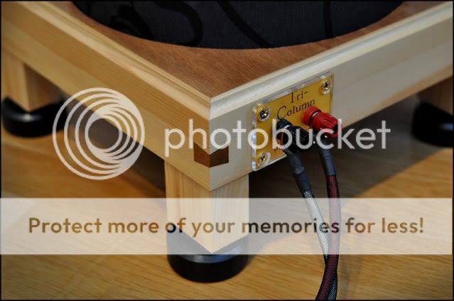
Here some pix of my refurbished SCA-35 together with my Rex Baldock Tricolumn parabolic horns
Btw thanks Dave for the EFB-regulator.
I tryed original bias, regular bias with balance pot, and finallt the EFB-regulator, wich sounds great.
I built the EFB-reg with the four separate bias adjustment pots and ended up with a Ia of 34mA sounding best to my ears

Built-tread in swedish:
HiFiForum.nu - Pix - Dynaco SCA-35. En gentleman i ny kostym

Rex Baldock Tricolumn parabolic horns with Philips 9710 Alnico driver:
These speakers are a great match to the SCA-35 using no filters hence really sensitive and easy to drive.

Built-tread in swedish:
HiFiForum.nu - Pix - Rex Baldock Tricolumn, Paraboliska horn
Pix
Sweden
Here some pix of my refurbished SCA-35 together with my Rex Baldock Tricolumn parabolic horns
Btw thanks Dave for the EFB-regulator.
I tryed original bias, regular bias with balance pot, and finallt the EFB-regulator, wich sounds great.
I built the EFB-reg with the four separate bias adjustment pots and ended up with a Ia of 34mA sounding best to my ears
Built-tread in swedish:
HiFiForum.nu - Pix - Dynaco SCA-35. En gentleman i ny kostym
Rex Baldock Tricolumn parabolic horns with Philips 9710 Alnico driver:
These speakers are a great match to the SCA-35 using no filters hence really sensitive and easy to drive.
Built-tread in swedish:
HiFiForum.nu - Pix - Rex Baldock Tricolumn, Paraboliska horn
Pix
Sweden
Racer -- I am finishing up moving to a new location, so all of my material is still packed up for now. I should be able to get to it in a few days and can help with the phono board connections.
Regarding the positive feedback loop, there is no doubt that when that concept is used, the phase splitter must be adjusted to account for it, since it is the source of the feedback. But its purpose is not to balance the phase splitter itself. Its sole purpose is to increase the gain of the input stage to maximize the global NFB level available in conjunction with the targeted input sensitivity level.
In the Dynaco amplifiers, the splitter's balance is determined by the value of the plate and cathode resistors used in the splitter circuit. When a positive feedback loop is NOT used (as in the case of the MK II, MK III, MK IV, MK VI and Stereo 70), you will note that the plate and cathode resistors for the phase splitter are exactly equal. When the positive feedback loop IS used (as with the ST-35 and SCA-35), the cathode resistor of the splitter is raised in value slightly over that of the plate resistor, to account for the impedance of the positive feedback loop connected there. When that impedance is accounted for with the higher cathode resistance, the overall effective resistance at the cathode is then identical to the value of the plate resistor used, so that balanced drive is achieved.
Now, all that being said, Dynaco did put out their own hype about the capacitive NEGATIVE feedback loop from the "bottom" output tube screen connection back to the cathode of the input tube, saying its purpose was to help balance the phase splitter. It is an important loop in the overall design, providing the necessary response roll off of the amplifier circuit proper (which does not include the OPT), so that the main NFB loop (which does include the OPT) will remain stable in the face of capacitive loads applied to the amplifier. However, in reality, it has no more to do with the balance of the actual phase splitter than the main NFB loop does. At the time these amplifier's were introduced, the "split load" phase inverter was under much criticism by those who (incorrectly) felt that this type of inverter was inherently unbalanced at high frequencies. It can be if the following stage loads are not identical at all frequencies as well, but the inverter itself is not inherently unbalanced. However, since the little capacitive loop from the screen connection was quite unique at the time, and the criticism of the inverter was in full play, Dynaco tried to avert criticism of its use by saying that the capacitive loop helped to balance its performance across the entire audio spectrum. It was all pure hype to be sure, and required only because of the misconception in play about the concertina's performance -- but it certainly worked, as their sales and history certainly shows.
I hope this helps clarify the action of the positive feedback loop that Dynaco used in SOME of their designs, versus that of the capacitive negative feedback loop from the screen grid that they used in ALL of their commercial designs.
I'm sorry you ended up with the wrong Russian tubes for your amp. Hopefully, if you cannot use them otherwise, you can resell them to cut your losses. The EL84M is the tube you want, and has proven to be capable, durable, and sounds good as well.
Pixworld -- Thanks for the kind words about my EFB modification. If you have the facilities available to you to measure your amplfier's performance, it would be instructive to watch the THD or IMD produced as the bias is adjusted when the EFB modification is used. During my initial development work, I used more sets of output tubes than I care to remember in determining the best current draw to specify as the target quiescent operating point. The average, and most often actual low distortion point was 27 ma per tube. As I recall one set nulled at as low as 25 ma, but in no case was more than 29 ma required for a null. The vast majority of sets (at least a dozen or so) nulled very nearly dead on at 27 ma.
There will be no damage caused by running the tubes at 34 ma when EFB is used, but I can virtually guarantee that distortion is significantly elevated at that level, and, you are not getting the benefit of the increased tube life that the lower quiescent level provides. I just wanted to make sure you were aware of these facts as you determine what setting is best for your needs.
Your SCA-35, speakers, and installation look really great, and I'm sure sound equally great as well!
Dave
Dave, the 6P15P's won't go to waste. I bought a Sansui AU-70 chassis with, I think, tango transformers. It was a pentode amp. So that's four of them right there. It was driven by a pair of 6AN8's. Which I have because I originally bought them for the SCA before I decided to use ST boards.
And I even found a use for some very low impedance 20 watt OPT's I salvaged from some old Magnavox consoles. They can be driven by a pair of 6550's in triode class A.
Its only a loss if you don't hang on to it long enough to find a use for it. Tubus Packratis!
Kevin
And I even found a use for some very low impedance 20 watt OPT's I salvaged from some old Magnavox consoles. They can be driven by a pair of 6550's in triode class A.
Its only a loss if you don't hang on to it long enough to find a use for it. Tubus Packratis!
Kevin
- Status
- This old topic is closed. If you want to reopen this topic, contact a moderator using the "Report Post" button.
- Home
- Amplifiers
- Tubes / Valves
- SCA-35 Dynaco