Balanced tube preamp for class D power amps:
Two of my power amps (mono blocks) are made of B&O’s IcePower class D modules. Compared to the tube power amps that I’ve got, these B&O’s have low input impedance and the inputs are balanced (3V rms for full power). My current tube preamp is on its best seeing high loads and does not feature balanced output. So what I’m aiming for is a tube preamp with balanced output, capable of driving loads well under 10k and a gain of ~10dB
The easiest way for converting a high impedance single ended signal into low impedance balanced signal is, as far as I see it, a step-down transformer. A 4:1 step-down will reflect 20k at the primary side when loaded with 1200 ohms. The 4:1 step-down will also have a gain of –12dB so if I want an overall gain of 10dB the driver have to add +22dB. If I use a setup with a triode in common cathode configuration with the step-down transformer as load, tubes like ECC88, ECC99, EL84, parallel 6SN7 etc will fit in. I think I’ll give the EL84 as triode a go. It’s a well-proven audio tube with low distortion and quite low plate resistance (about 2k in triode mode), it’s still in production and not that expensive.
Looking at the schematic you will see that the driver stage is so called ultrapath with the cathode decoupled to B+ with a film capacitor. Except for that it’s straightforward common cathode. Estimated gain in the driver is 14-15x (~23dB).
The balanced output from the transformer is floating, terminated with a resistor (1k2) to maintain a minimum load and the high frequency response of the transformer.
The output impedance will be something like rp*(4:1)^2||1200. If we estimate the EL84’s rp to be 2k, Zout will be ~110 ohm (plus transformer loss). This should be low enough to drive loads down to 1-2k.
The frequency response is limited at the low end of the transformer’s induction and at the high end of the EL84’s miller capacitance and resistance in the potmeter and grid resistor. The specifications from Sowter and Phillips are 40H and 10pF. So in theory that should give:
Fc(low)={(rp*Rl)/(rp+Rl)}/(2Pi*L)={(2000*20000)/(2000+20000)}/(2Pi*40)
Fc(low)=7Hz at the low end and
fc(high)={1/(2pi*Cm*Rg||Rpot/2)}=22kHz at the high end with the potm at the worst possible position. Not that high, but if I reduce the value of the pot to 50k I'll double the fc(high).
At the drawing board it looks like that I have meet the requirements of Zout and gain. The max output swing is estimated to be about 20V rms.
Any comments?
Jan E Veiset
Two of my power amps (mono blocks) are made of B&O’s IcePower class D modules. Compared to the tube power amps that I’ve got, these B&O’s have low input impedance and the inputs are balanced (3V rms for full power). My current tube preamp is on its best seeing high loads and does not feature balanced output. So what I’m aiming for is a tube preamp with balanced output, capable of driving loads well under 10k and a gain of ~10dB
The easiest way for converting a high impedance single ended signal into low impedance balanced signal is, as far as I see it, a step-down transformer. A 4:1 step-down will reflect 20k at the primary side when loaded with 1200 ohms. The 4:1 step-down will also have a gain of –12dB so if I want an overall gain of 10dB the driver have to add +22dB. If I use a setup with a triode in common cathode configuration with the step-down transformer as load, tubes like ECC88, ECC99, EL84, parallel 6SN7 etc will fit in. I think I’ll give the EL84 as triode a go. It’s a well-proven audio tube with low distortion and quite low plate resistance (about 2k in triode mode), it’s still in production and not that expensive.
An externally hosted image should be here but it was not working when we last tested it.
Looking at the schematic you will see that the driver stage is so called ultrapath with the cathode decoupled to B+ with a film capacitor. Except for that it’s straightforward common cathode. Estimated gain in the driver is 14-15x (~23dB).
The balanced output from the transformer is floating, terminated with a resistor (1k2) to maintain a minimum load and the high frequency response of the transformer.
The output impedance will be something like rp*(4:1)^2||1200. If we estimate the EL84’s rp to be 2k, Zout will be ~110 ohm (plus transformer loss). This should be low enough to drive loads down to 1-2k.
The frequency response is limited at the low end of the transformer’s induction and at the high end of the EL84’s miller capacitance and resistance in the potmeter and grid resistor. The specifications from Sowter and Phillips are 40H and 10pF. So in theory that should give:
Fc(low)={(rp*Rl)/(rp+Rl)}/(2Pi*L)={(2000*20000)/(2000+20000)}/(2Pi*40)
Fc(low)=7Hz at the low end and
fc(high)={1/(2pi*Cm*Rg||Rpot/2)}=22kHz at the high end with the potm at the worst possible position. Not that high, but if I reduce the value of the pot to 50k I'll double the fc(high).
At the drawing board it looks like that I have meet the requirements of Zout and gain. The max output swing is estimated to be about 20V rms.
Any comments?
Jan E Veiset
I would not bypass the Cathode Resistor with Ultrapath.
If I understand correctly, the ultrapath cap is the bypass.
Multiple caps simply form an AC voltage divider between b+ and ground.
I would not load the transformer secondary, at least to the level you show. Triodes will have much lower distortion when not loaded. The transformer may have a HF peak, but Kevin over @ K and K generally recommends that you try it without loading first.
Hope this helps.
Doug
DougL said:I would not load the transformer secondary, at least to the level you show. Triodes will have much lower distortion when not loaded. The transformer may have a HF peak, but Kevin over @ K and K generally recommends that you try it without loading first.
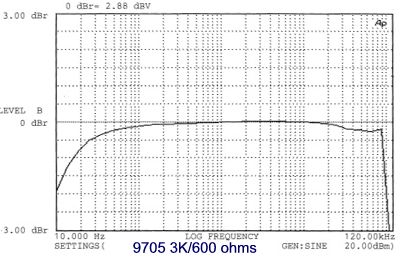
The 1k2 resistor at the secondary side reflects a ~20k primary load - I don’t think that is a heavy load for the EL84? Sowter don't recommend running the 9705 without load, here is the frequency response for 9705 terminated with 600 ohm (and rp=3k):
In my case, if the input resistance of the power amp is 4k and the terminator resistor is 1k2, still this will reflect a plate load of no more than {4k||1k2*(4:1)^2} or about ~15k ohm.
Jan E Veiset
7 times Rp doesn't seem really excessive.The 1k2 resistor at the secondary side reflects a ~20k primary load - I don’t think that is a heavy load for the EL84? Sowter don't recommend running the 9705 without load, here is the frequency response for 9705 terminated with 600 ohm (and rp=3k):
I was thinking 4:1 . My bad.
However, it is an easy experiment to change.
Doug
Joel said:I'd like to see a grid stopper on a high gm tube like the EL84. 470 ohms should be good.
Yes, a stopper won't hurt.
I also included a level/balance pot after the volume pot in the current schematic.

DougL said:However, it is an easy experiment to change.
True. When it comes to transformers it's hard to know the exact transfer function until you have tested it in the actual circuit.
Jan E Veiset
- Status
- Not open for further replies.