i ran a cross this on an ee site does this have any real place in audio does anybody know. seems kind of cool to me eliminating pt.
here is the link
http://www.du.edu/~etuttle/electron/elect27.htm#117
also here is the circuit he mentions
here is the link
http://www.du.edu/~etuttle/electron/elect27.htm#117
also here is the circuit he mentions
Attachments
 ')
')AtomiKM said:i ran a cross this on an ee site does this have any real place in audio does anybody know. seems kind of cool to me eliminating pt.
here is the link
http://www.du.edu/~etuttle/electron/elect27.htm#117
also here is the circuit he mentions
Really cheap record players (like those you give to kids to keep them away from the good stuff) used amplifiers just like that.
Expect Lo-Fi operation: lots of hum from the high voltage heaters and typically poor filtering of the DC rail, no gNFB to tame pentode nastiness (and it's probably a really nasty pentode anyway) very inadequate output xfmr.
It was never designed to sound good, just to be dirt cheap to manufacture. For the cost of making that thing, you can get some chip amps that'll sound far better. Also, there won't be any
 experiences due to the lack of isolation from the AC mains.
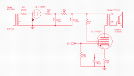
Attached is a safe Schematic for the 117N7
The rectifier diode looks backward.
The short to ground and arrow are confusing to less-experienced builders.
Which is actually 70% underrated since the heater is 90mA and the operating current is ~56mA making the needed transformer overhead for that DC around 78mA. Also, what's the point of R1 and R2? Because you are running this on a transformer you shouldn't need either one of those as the winding resistance of the secondary provides your current limiting. Run the recommended 40uF filter cap straight on the rectifier and drop DC from there.
The pentode used in these isn't bad if you are okay with low power. As with a lot of series string power tubes they were optimized for low-voltage which means piddly power. They are, however, surprisingly pleasurable to listen to.
Since the pentode side of the tube gets grounded it shouldn't be too bad on hum with AC heaters as the pentode likely only sees about 60V of that. Plus if it does hum it isn't hard to inject some extra AC to cancel it out.
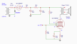
Thanks for the advice, I actually used a 250mA transformer but I thought a 100mA would also work, you're saying the diode current is in parallel to the heater current not coming from the heater current? As for the filter I used 2 RC filters to reduce the ripple better, you think just a cap would be just as good?
Yes, diode current is parallel to the heater.
I'm saying the resistors immediately before and after the rectifier shouldn't be there. You still need the CRC power filter but you want cap #1 right after the rectifier without a resistor before it. This gives you the highest Cap 1 voltage so you have more to drop to cap 2 and therefore less hum.
I'm saying the resistors immediately before and after the rectifier shouldn't be there. You still need the CRC power filter but you want cap #1 right after the rectifier without a resistor before it. This gives you the highest Cap 1 voltage so you have more to drop to cap 2 and therefore less hum.
Wow!
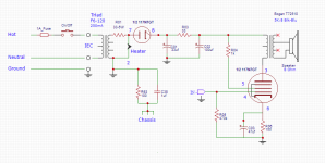
These incomplete circuits make me nervous, some will try and duplicate it verbatim, without regard to the following:
Use a 3-wire grounded outlet, 3-wire IEC power cord, and 3-wire IEC input socket on the amp.
Use Hot and Neutral to run the primary circuit, and be sure to add a fuse and switch in series with the primary.
Order of connections, Hot, Fuse, Switch, Primary, Neutral.
Ground the amp commons (bottom of DC power, bottom of self bias resistor, the bottom of the output transformer secondary, and the metal chassis). Connect all these to the IEC socket ground connection. Your signal input connector also needs to connect its ground to this same ground.
This may be a little record player, but we are not in the 1950s anymore.
Failure to accomplish the above measures will cause former UL employees to turn over in their graves!
Last edited:
The more "modern" (early 60's) equivalent circuit is a pair of 60FX5's with a sand state rectifiers. This was the early 60's STEREO version of the cheap record player. It and the 117N7 version were fed by a ceramic "crystal" pickup (phono cartridge) whic was the fidelity limiting factor anyway. The 60FX5 has enough Gm to be driven to a watt or so from a CD player. You can not drive any single tube amp directly from a modern turntable, they put out milivolts, and not very many of them.
The circuit is on page 698 of the RCA RC-30 tube manual.
Spend the extra $6 and get a Triad N-68X. It is a 50 VA transformer for $15.81 at Mouser. I have a 4 tube 4 watt series string guitar amp running from one. Its been alive for 3 years and I haven't blown it up yet.
Do pay attention to the proper grounding comments made by 6A3summer. This MUST be followed if you plug anything metal into the amp like a CD player or a guitar. A shorted part can electrify the whole setup.
UCL82 (50BM8) was the most common choice on cheapest record players here. This tube is still pretty cheap now and has more gain and power (2-3w). I attach a circuit of the era. The autotransformer was often replaced by a extra winding of the motor itself. On earlier designs, UY85 was the rectifier of choice. As funny note, this totally unsafe device was targeted to a market that did not used polarized plugs, so the user manual stated that "care should be applied" connecting wires. This device has a extra piezo cristal plug for the tape recorder. I guess that after the first few 230V electrical shocks, the surviving users were well trained not to touch any wire when the power cord was connected to the outlet.
The 117N7 tube is intriguing due to the rectifier and power output in a single tube, so a silicon-less single tube amplifier could be made. The diode/tetrode combination has later been used on B/W TV sets, with damper and sweep function in the same tube. This will enable more audio power.
The 117N7 tube is intriguing due to the rectifier and power output in a single tube, so a silicon-less single tube amplifier could be made. The diode/tetrode combination has later been used on B/W TV sets, with damper and sweep function in the same tube. This will enable more audio power.
Last edited:
- Status
- This old topic is closed. If you want to reopen this topic, contact a moderator using the "Report Post" button.
- Home
- Amplifiers
- Tubes / Valves
- 117v heater tube 117n7