I haven't seen this one yet so thought to throw it to the forum for comment. It appears to work very well on the bench in early testing.
The concept is simple enough, use a CCS driving a resistor to generate a bias voltage. See below. 10ma through 10kohm results in 100 volts. The IXYS doesn't care about load so the circuit can be scaled for any device. Want to do a 6BQ5? Change the 10K to around 1K. The CCS is loafing either way. I always use a 10-turn on these chips to make them adjustable, which works perfectly here for fine tuning bias.
The grid supply requires a bit higher voltage. The voltage swing seen by the CCS is the driver output resistively divided by the grid and bias resistors, a fraction of what it would see as if used as the preceding driver's plate load. The IXYS CCS's impedance if well over 5 meg midband, even without a bypass cap across the 10 k resistor the power supply ripple rejection is over 50 dB typically. From the tube's perspective looking back out the grid, it sees almost nothing of the grid supply at all, just the grid leak and bias resistors. If you want insane PS ripple rejection bypass the 10K, a small film will provide a very low corner frequency.
The IXYS starts conducting the instant it sees voltage. The light load and instant response means a very quick bias turn-on. Finally, and hopefully, the reputed failure mode for these chips is a dead short. Should it fail the output tube would be instantly biased off.
The intention here was to effectively remove a cap from the audio path but it's not mandatory. I won't know for sure until I light up the B+ on an 813 but the technique seems win-win at the expense of a little extra complication. Thoughts and opinions appreciated.
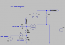
Attachments
rdf said:Finally, and hopefully, the reputed failure mode for these chips is a dead short.
My, ahh, er, "tests" confirm this.
mach1 said:rdf,
The problem I see is that the tube being biased may not like having current drawn from its grid in this A2 like situation. However, I have no experience with 813s.
regards
pm
Voltage is voltage. If the grid goes positive, grid current will flow. Has nothing to do with how the bias voltage is derived.
Sheldon
The way that rdf has it configured, I1 and R1 provide a negative grid bias. No current is yanked out of the grid. The 10K provides the sole current path. I would be tempted to add the filter cap too. The combination of the current source and the low impedance to ground would ensure a very quiet bias supply. Should work.
rdf said:Finally, and hopefully, the reputed failure mode for these chips is a dead short.
Tubelab has noted some issues with oscillation of these chips which he quelled with a 1K resistor on the G pin I think.
sawreyrw said:rdf,
Something is wrong here. Where does the current come from for the CCS? It can't make current by itself.
If the CCS could generate current without external bias, (which it can't) the voltage across the 10K resistor would be -1oo volts.
I guess this won't work.
Rick
It should work. The 10K does indeed create a -100 volt grid supply, which is what rdf predicted. As rdf says, you can change the 10K to anything smaller to derive smaller grid bias voltages. You could even make the resistor a potentiometer (one capable of handling DC current) and then adjust the bias. Currents must always flow in a loop. The power supply (a simplified simulator depiction) on the left provides the raw voltage (and current), and then current flows through the CCS, through the 10K resistor, and back to the PS through ground. Actually I described the direction of flow of electrons, while a conventional current description says the current flows in the opposite way, but it's still the same loop idea.
sawreyrw said:rdf,
Something is wrong here. Where does the current come from for the CCS? It can't make current by itself.
If the CCS could generate current without external bias, (which it can't) the voltage across the 10K resistor would be -1oo volts.
I guess this won't work.
Rick
Here's another way to look at it: Shorthand is used when talking about current sources. But in plain language, the chip you see here is actually not a constant current "source", it's a constant current Regulator. When you put the regulator in series with a battery or other power source, the combined source and regulator constitute a constant current Source. If you put a resistor in the current loop, you have a voltage drop across the resistor as determined by Ohms law - V=IR. This assumes, of course that the battery or power supply can source (or provide) the needed current at the required voltage.
Sheldon
Thanks all for the input! One downside I see in hindsight is that's an extremely well regulated bias supply, therefore no accomodation for line voltage variances. Otherwise with a trim pot mounted on the CCS the range of voltage variance is as large as you care to make it. I haven't been able to confirm noise performance yet because the readings are swamped by the hum of an AC filamant 813.
BTW, I like Brian's idea of inserting a pot in series with the 'bias resistor'. If wired properly the failure mode would again be towards full negative bias, preserving the output tube from a pot failure.
BTW, I like Brian's idea of inserting a pot in series with the 'bias resistor'. If wired properly the failure mode would again be towards full negative bias, preserving the output tube from a pot failure.
rdf said:I haven't been able to confirm noise performance yet because the readings are swamped by the hum of an AC filamant 813.
Got a couple extra of those current regs., adjustable types? Or do they have high enough current ratings?
Sheldon
Hi Sherman, I'ld love to try a current reg but the 813 wants 5 amps at 10 volts. An IXYS wouldn't have time to register surprise as it vapourized. The driver stage really wakes up at >1000 volts B+ so I'll try cathode bias and a balance pot first. Now that I think of it, testing the CCS bias circuit's noise will be a trivial excercise with my current test mule. I may get around to it tonight and will post the results.


- Status
- This old topic is closed. If you want to reopen this topic, contact a moderator using the "Report Post" button.
- Home
- Amplifiers
- Tubes / Valves
- CCS Grid Bias