Does anyone have any thoughts on using a 6AS7 on the output of either something like the tubelab se, or a small low watt guitar amp? Is the plate resistance too low, or would it be better to leave out the cathode bypass cap? I remember reading somewhere that they were essentially a pair of indirectly heated 2a3's in a single tube, but that may have just been someone's marketing.
I don't have any direct experience of 6080 amplifiers but as nobody else has answered...
There's very little similarity between half a 6080 and a 2A3 other than that they're both triodes and about the same anode rating. Mind you, they're cheap... Because they're intended for series regulator use close adherence to published anode curves wasn't necessary, but for SE use that shouldn't be too much of a problem. The low anode resistance means you need a lower primary impedance for the output transformer, making it easier to make a good one. Keep the cathode bypass capacitor.
There's very little similarity between half a 6080 and a 2A3 other than that they're both triodes and about the same anode rating. Mind you, they're cheap... Because they're intended for series regulator use close adherence to published anode curves wasn't necessary, but for SE use that shouldn't be too much of a problem. The low anode resistance means you need a lower primary impedance for the output transformer, making it easier to make a good one. Keep the cathode bypass capacitor.
You can build everything with that tube. SE, PP in all classes, CathodeFollower, PPP, Circlotron, Horizon, SEPP, OTL.....
But be careful when paralleling the tubes. You will need matched tubes.
An Advatage is the very low load impedance and output impedance which provides good damping factor and a cheap output transformer.
Connected as Cathode Follower and with big amount of global Feedback, the damping factor is amazing good and the tube can drive every kind of Subwoofer. Of course a cheap solid state Amp is better suited for this job.
The best is when you buy a box of 100 pieces of the cheap russian 6H13C, thats the russian equivalent of the 6080. Doesn't cost that much and you can match them yourself. It's a nice Cockebottle tube.
But they need to be driven properly.
Heres a nice schematic of an SEPP, it was successfull built by a german guy:
The Article (PDF)
The AMP
best regards, Manta
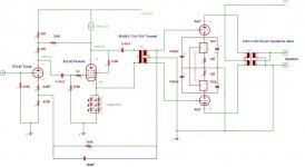
Here is my try on a friend schéma. My SEPP is based on ECC83 and 6080/6AS7G.
Rest with many pictures are here
This amp (i need to built second bloc) sound very good to my ears, better than my solid state one. A realy low caost fine project.
Marc
An externally hosted image should be here but it was not working when we last tested it.
Rest with many pictures are here
An externally hosted image should be here but it was not working when we last tested it.
An externally hosted image should be here but it was not working when we last tested it.
This amp (i need to built second bloc) sound very good to my ears, better than my solid state one. A realy low caost fine project.
Marc
the_manta said:
Heres a nice schematic of an SEPP, it was successfull built by a german guy:
The Article (PDF)
The AMP
best regards, Manta
They're not the same circuit. right?
also do you have a clearer drawing for the first link? I could barely read the values on the schematics.
thank you
")
Idefixes said:Here is my try on a friend schéma. My SEPP is based on ECC83 and 6080/6AS7G.
This amp (i need to built second bloc) sound very good to my ears, better than my solid state one. A realy low caost fine project.
Marc
how many watts does can it output? thank you.
jarthel said:
how many watts does can it output? thank you.
Between 5 and 10w it depend on 6AS7G cathode resistor value.
Marc
Idefixes said:
Between 5 and 10w it depend on 6AS7G cathode resistor value.
Marc
lower the resistance the higher the wattage?
jarthel said:
lower the resistance the higher the wattage?
Yes but pay attention to max plate dissipation.
Marc
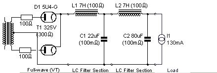
check this site:
http://www.audiokit.it/ITAENG/KitElettr/MEGA/Lilliput/Lilliput.htm
I've made this amp. It's a cheap but good sounding amp for high efficiency speakers.
The PS I used:
http://www.audiokit.it/ITAENG/KitElettr/MEGA/Lilliput/Lilliput.htm
I've made this amp. It's a cheap but good sounding amp for high efficiency speakers.
The PS I used:
Attachments

If your still interested in a 6080 amp, I could share my experiences of building a PP one with toroidal mains transformers as interstagers. Mains toroidals for outputs. Driven by a partial feedback ECL82. Hard to drive tubes in this configuration.
Definately consider CCS for the output cathodes - makes life simpler, but they need bypassing.
Been running reliably now for about 7 months. Sounds really good. Beats my RH807 by a long margin (though that tempting to listen to).
Let me know.
Shoog
Definately consider CCS for the output cathodes - makes life simpler, but they need bypassing.
Been running reliably now for about 7 months. Sounds really good. Beats my RH807 by a long margin (though that tempting to listen to).
Let me know.
Shoog
Shoog said:
Let me know.
Shoog
interested.
also could you show the mods needed to use CCS and what is the CCS output?
thank you very much
The CCS I have used are based on LM317's. More than adequate for the appllication (sound quality is all down to the bypassing). A very good write up can be found over at tubecad. I used one LM317 for each cathode, this eliminates the need for bias adjustment. Its a technique that is used in the Vacume State high end amps.
Shoog
Shoog
Shoog said:The CCS I have used are based on LM317's. More than adequate for the appllication (sound quality is all down to the bypassing). A very good write up can be found over at tubecad. I used one LM317 for each cathode, this eliminates the need for bias adjustment. Its a technique that is used in the Vacume State high end amps.
Shoog
could you share the schematic of the amp and the related tubecad CCS circuit?
can you also point where/what parts are replaced by the CCS?
also what's the required current output of the amp?
thanks again
The beauty of placing seperate CCS 's in each cathode is that it allows you to tightly control the static current going through the two triodes in the PP pair. Hence no need to match the triodes, and no need to adjust the bias because it finds its own bias point to pass the current which the CCS is forcing through it.
Things are obviously not perfect because the triodes are not matched and they will therefore have slightly different responses and hence the two sides of the PP waveform will be slightly different. This will lead to a smudging of the combined waveform.
My personal experience is that this is a very small issue - far outweighed by the benefit of current balance in the output transformer. The sound is clean and clear to a quite unexpected degree. I would use this technique in any future project, PP or SE.
I have my 6080 tubes set to pass 100mA at about 100V plate to cathode. Bias settles to about 28V. This Allows you to use easily availble mains toroidals as output transformers. I have had no failures since the initial testing phase, and can see these tubes running for years at a time.
Here is a link to the Tubecad article and I will attempt to post a schematic.
http://www.tubecad.com/february2000/page6.html
Unfortunately all the schematics i drew up are from the work in progress stage and won't be totally accurate.
Shoog
- Status
- This old topic is closed. If you want to reopen this topic, contact a moderator using the "Report Post" button.
- Home
- Amplifiers
- Tubes / Valves
- Transformer coupled 6AS7/6080