I have a couple of Robert/Akai mono block amps that I'm slowly converting into mic pres (see my earlier thread).
I have a question concerning grounding in tube amps. The existing power cord is only 2 wires...so no ground. How do i add a ground, is the metal chassis "groundable" without affecting the amps operation? When I come to add the balanced XLR sockets and input and output tannies what constitutues the required grounding for those items under these circumstances?
I don't want to risk electrocuting a singer in my studio. Also since the items will be racked, the chassis via the face plate will be directly in contact with the rack mounting rails and hence other equipment...any problems forseen?
BTW, I don't have the amp model numbers or any schematics but the units were very well prepared in their present state by a retired audio engineer.
I see conflicting advice when i do a search on this subject, some say a main ground close to the power transformer plus a second "star" ground terminal as far away from the main ground as possible with indiviual ground wires going to it from the variuos componenets that require grounding. The others say ONLY one ground!
HELP!!!
HELP!!!
Here is what I do- I usually use an IEC inlet (like the power cord connector on the back of a computer). Solder a relatively heavy gauge wire to the 3rd connector and then attach it to the chassis near the power inlet. This is 'safety ground'. If for any reason your chassis becomes 'hot' this ground gives a lower resistance path to earth than your body.
I run the AC 'hot' lead from the inlet to an appropriately sized fuse and then from the fuse to the on/off switch. The AC 'neutral' can go directly to the PTX from the inlet, though some people prefer to switch using a DPDT and switch both the hot and neutral.
Make a separate ground pointnot connected to the chassis for your power ground. Then make a 3rd separate ground point also not attached to the chassis for your signal ground. Lastly run a single heavy gauge copper wire from each of these two (power and signal) grounds to the safety ground.
It works for me.
"Make a separate ground pointnot connected to the chassis for your power ground. Then make a 3rd separate ground point also not attached to the chassis for your signal ground. Lastly run a single heavy gauge copper wire from each of these two (power and signal) grounds to the safety ground."
Thank you for responding.
OK, treat me as a really dumb individual and expand on this statement with a lot of extra detail. When you talk power ground what exactly do you mean? If the power ground and signal ground are not immediately grounded to the chassis, where do you put their ground terminals? Do you use isolated star terminals (isolated from the chassis) and then link them with heavy duty copper wire to the safety ground?
I'm a little lost I'm afraid.
The circuit's ground and safety ground are two separate things. In theory, the circuit ground doesn't even have to connect to the safety ground. The use of the term "ground" for both functions is very confusing to many people.
First, let's start with what Sherman said. His recommendation of tying the IEC ground directly to chassis at the input is precisely what you need to do for safety. And his recommendation to have circuit grounds isolated from the chassis is also exactly what you want. Now, the circuit ground can and in many cases should be eventually connected to the chassis, but this should happen at one and only one point, usually at the input. If a ground loop occurs with other equipment, the circuit ground can be lifted from the chassis (safety) ground. Under no circumstances should the safety ground be lifted!
Once this is established, there are several possible grounding schemes (e.g., star, bus, star + bus, ground plane...) from which to choose.
There's a very nice explanation with pictures and some practical suggestions in the excellent book "Building Valve Amplifiers." The author shows a neat trick for ground lifting using a telephone plug and some illuminating photos. I would also highly recommend the white papers on grounding and isolation posted at the Jensen Transformers website, and the articles and examples at Aiken Amplification's site.
SY said:]The circuit's ground and safety ground are two separate things. In theory, the circuit ground doesn't even have to connect to the safety ground. The use of the term "ground" for both functions is very confusing to many people.
...
Good point. Maybe we should use the term "earth" like the Brits for the "safety ground" and just use "ground" for circuit grounds. (As if we will change after a hundred years or so.
 )
)So is the star ground terminal or the buss ground insulated from the chassis? ie. if I use a section of copper buss do i mount it with insulated fasteners, run all the individual component copper ground wires to it and then one main ground wire over to the main power ground terminal ?
The existing grounds on the Roberts/Akai mono blocks for say the 1/4" unbalanced jacks are prsently just to the chassis, I assume that I would re-route them to the buss? What about the main power transformer ground?
The existing grounds on the Roberts/Akai mono blocks for say the 1/4" unbalanced jacks are prsently just to the chassis, I assume that I would re-route them to the buss? What about the main power transformer ground?
Actually, there are some standards. Being an engineer, standards are extremely important, and are there for a reason. Typically standards are adopted more for personal safety, compliance, and specification than for design, but nonetheless we can see how a lack of standards here adds to confusion.
In my experiences, the attachment shows a proper symbolic nomenclature for all generic electronic equipment.
The third prong of your IEC connector is 'earth ground', or simply 'earth'. The implication is that at some point this connection is directly bonded to earth.
The top plate/chassis of your amplifier is 'frame ground', or better yet, simply 'frame' (IEEE frowns on the use of 'frame ground' due to its misuse). While not technically necessary, it is required by code that your 'frame' be tied to 'earth'. The exception to this code requirement is when a piece of UL listed equipment (none of which we DIY-ers make) is double-insulated. Therefore, you must tie 'frame' to 'earth', no exceptions. Frame should also include your transformers' chassis as well.
The last entity is circuit common. It is incorrect and tragic to call the negative rail of your B+ 'ground', for there is absolutely no requirement that it be 'earthed'. The shield of your input RCA or XLR is almost universally tied to circuit common. Ii is not necessary that this be tied to either 'frame' or 'earth', but there are reasons to do so. We should note that in dealing with a B+ supply of a few hundred volts, it is quite feasible for our circuit common to float to voltages we as humans will not like. So some coupling of circuit common to earth is wise. This could be through a capacitor, resistor or jumper.
This produces some difficulties, however. Typically we have a CD player, turntable, preamp, receiver, etc in the audio system. Without interstage transformers, there is the chance of having multiple 'earths' of our 'circuit common' through the various components. This increases our chances of ground loops and noise injection. It is my recommendation to float circuit common on all devices but one, and if you feel the need to bond any additional, do it with both/either a ceramic cap and Meg sized resistor.
Note that most CD players bond their circuit common (shield of RCA) to the frame. The cord is typically 2 wire (no earth connection). But there is some coupling between the case and your furniture/house/other components to earth. The whole problem continues to exacerbate. If I ever get around to building my own DAC w/ tube output, I will eliminate this bond, and keep my circuit common floating except at the amp.
Moral of the story is that transformers are beautiful things. Not that you should use an interstage transformer only for isolation, but it does indeed provide galvanic isolation very well.
Attachments
Hello Limey22,
A floating ground is isolated from the chassis. Buss grounding and star grounding are merely ground topology strategies which supposedly each have influence on the sound of an amplifier. In either star or buss grounding, the ground can be connected to the chassis or not.
BTW, I have heard many superior sounding amps that use the chassis for all their grounding, neither buss nor star.
At any rate, most amps use the chassis as part of the signal ground. You mention having a 1/4" phone jack. Check to see if the phone jack's ground is connected to the chassis. If it is not, then you have what is known as a floating signal ground. Make sure not to connect the chassis and signal ground if separate. You might introduce ground loop hum (whatever that means) or at worst a short circuit which may damage the amp.
With two wire AC cord, the manufacturer is hoping that the electrician conected the neutral to ground at the fuse/breaker box. (it is done in most homes. It is in both homes I have lived in). So there is a ground. (I am not sure if it is the bigger of the two polarized AC plug prongs).
As far as safety is concerned, as SY said you will want to make sure, if you have three wire AC, to connect the green wire (earth, true ground) to the chassis.
In addition to what SY has said about the confusing "ground", there is also a signal ground. So one can have three grounds. The power supply circuit ground, the signal ground, and the safety ground, which is the chassis and as Sherman said should be called "earth". In fact, the schematic symbols for circuit ground and safety ground or earth are actually different.
The difference between signal ground and circuit ground is that signal ground is isolated from the DC of the circuit by either a transformer or capacitors.
Signal/circuit ground is this:
|
---|---
-----
--
and "earth" is this:
|
-----|-------
/ / / / / /
I hope these come out. If not, the upper one is a vertical line birsecting a horizontal line, with two other lines spaced below the to line, but each being shorter than the previous one.
The bottom one is a vertical line bisecting a horizontal line with diagonal lines across the bottom.
Gabe
I would like to clarify some things, with all due respect. Please do not get offended.
There is no such thing as a floating ground, unless it is a wire INTENDED to be grounded, but there is an unintentional open i.e. there is a malfunction that causes what SHOULD be grounded to float. Circuit common may float, but ground does not. This is the very point SY and I were making, there is too much improper naming out there, confusion is added. I would clarify your statement by saying "circuit common is floating, or isolated, from the chassis"
Again, this is inaccurate naming. 'Floating shield' or 'floating circuit common', maybe, but not a 'floating signal ground'. Any floating ground is a bad thing, period. If you design it that way, it's clearly not a ground, it's common.
I don't know if I understand you here, but if a piece of equipment is only provided with a 2-wire cord, you cannot connect the neutral to your chassis, even if it is bonded to earth back at your service (which is required by Code). This is very important !! You can never connect the neutral in this manner, it must be isolated from personal contact. The only exception to this is you are permitted to bond the neutral of an electric dryer or electric stove to its chassis if a separate grounding conductor is not provided. This is an exception, however, and not the norm. In North America, you absolutely cannot ground (earth, bond) the neutral anywhere downstream of your service panel, especially to the chassis of electronic equipment.
I don't completely agree with your circuit symbols, but oh well. There will clearly not be a consensus until our generation is extinct. Maybe generation Z will figure it out.
No offenses, I hope
Gabevee said:A floating ground is isolated from the chassis.
There is no such thing as a floating ground, unless it is a wire INTENDED to be grounded, but there is an unintentional open i.e. there is a malfunction that causes what SHOULD be grounded to float. Circuit common may float, but ground does not. This is the very point SY and I were making, there is too much improper naming out there, confusion is added. I would clarify your statement by saying "circuit common is floating, or isolated, from the chassis"
If it is not, then you have what is known as a floating signal ground.
Again, this is inaccurate naming. 'Floating shield' or 'floating circuit common', maybe, but not a 'floating signal ground'. Any floating ground is a bad thing, period. If you design it that way, it's clearly not a ground, it's common.
With two wire AC cord, the manufacturer is hoping that the electrician connected the neutral to ground at the fuse/breaker box. So there is a ground.
I don't know if I understand you here, but if a piece of equipment is only provided with a 2-wire cord, you cannot connect the neutral to your chassis, even if it is bonded to earth back at your service (which is required by Code). This is very important !! You can never connect the neutral in this manner, it must be isolated from personal contact. The only exception to this is you are permitted to bond the neutral of an electric dryer or electric stove to its chassis if a separate grounding conductor is not provided. This is an exception, however, and not the norm. In North America, you absolutely cannot ground (earth, bond) the neutral anywhere downstream of your service panel, especially to the chassis of electronic equipment.
I don't completely agree with your circuit symbols, but oh well. There will clearly not be a consensus until our generation is extinct. Maybe generation Z will figure it out.
No offenses, I hope
zigzagflux said:I would like to clarify some things, with all due respect. Please do not get offended.
There is no such thing as a floating ground, unless it is a wire INTENDED to be grounded, but there is an unintentional open i.e. there is a malfunction that causes what SHOULD be grounded to float. Circuit common may float, but ground does not. This is the very point SY and I were making, there is too much improper naming out there, confusion is added. I would clarify your statement by saying "circuit common is floating, or isolated, from the chassis"
Again, this is inaccurate naming. 'Floating shield' or 'floating circuit common', maybe, but not a 'floating signal ground'. Any floating ground is a bad thing, period. If you design it that way, it's clearly not a ground, it's common.
I don't know if I understand you here, but if a piece of equipment is only provided with a 2-wire cord, you cannot connect the neutral to your chassis, even if it is bonded to earth back at your service (which is required by Code). This is very important !! You can never connect the neutral in this manner, it must be isolated from personal contact. The only exception to this is you are permitted to bond the neutral of an electric dryer or electric stove to its chassis if a separate grounding conductor is not provided. This is an exception, however, and not the norm. In North America, you absolutely cannot ground (earth, bond) the neutral anywhere downstream of your service panel, especially to the chassis of electronic equipment.
I don't completely agree with your circuit symbols, but oh well. There will clearly not be a consensus until our generation is extinct. Maybe generation Z will figure it out.
No offenses, I hope
OK, nomenclature notwithstanding, and definitely no offense taken, common is what it should be called. But it has been commonly called floating ground in many texts I have read...
http://en.wikipedia.org/wiki/Ground_(electricity)
http://www.answers.com/topic/floating-ground
http://www.phoenixcon.com/products/interface/db/datasheets/AnalogSignalProtection.pdf
http://www.sjgreatdeals.com/sgtpwr14.html
I am not in my lab, so I cannot provide the textbook references at ths moment... from reputable engineers and technicians. Are you saying they are ALL wrong? Perhaps so.
As for schematic symbols... you are right. I wish the texts would get their acts together!
The triangular shaped lines is earth, and the diagonal lined one is chassis. Signal ground is an empty upside down triangle.
As for the two wire connection, I was not suggesting that one connect the chassis to the neutral. Sorry if it seemed that way. I certainly never do. All I said was that there is a ground. In many older receivers, there used to be a cap or resistor connected to the neutral to take advantage of the ground for radio signal reception, and some chassis leakage to prevent unintentional shock. Ever touch the chassis of an older piece of equipment without the polarized plug and acidentally touch an old fashioned steam heat radiator? Quite a tingle there! Simply reverse the plug and the tingle goes away. That is why as you say the neutral is no longer connceted in any way to the chassis.
Thanks for the corrections!
Gabe
Gabevee said:from reputable engineers and technicians. Are you saying they are ALL wrong?
With humility, yes, they are all wrong. But not on the basis of my opinion, but on the basis of IEEE standards (Green Book, Emerald Book). Don't have references at this point, but they're there. There are even some references to vacuum tube designs, which used chassis grounds, and statements regarding the confusion this practice has caused.
If IEEE says it, then you, me, and other authors you may find will be wrong if we disagree, almost without exception. These guys know their stuff.
limey222 said:Sheez..if you guys can't agree, what chance do I have..I'm now totally confused
Actually, I think Gabe and I are in agreement, for the most part. Sorry to confuse you, but perhaps simple instructions will help you out.
1. Always connect the third prong to your chassis/top plate in one place.
2. Always bond the cases of your transformers/chokes/etc. unless you specifically know what you are doing and why you do not want to do this. Ideally, in one place, though typically they are bonded just due to their mounting arrangement.
3a. Usually connect the RCA shield/circuit common to the chassis (in one place).
3b. In instances where you are sure the shield is bonded to earth elsewhere, leave it isolated from earth/chassis.
3c. In instances where you are sure there is only one bond from shield to chassis, but you still get hum or noise, you have an error in your wiring.
4. Connecting shield/circuit common through a resistance or capacitor to chassis should only be done when you understand everything else in the posts above.
5. Any time you go through a transformer, you have isolated yourself from ground, and will want to produce a new bond. Best example is the output transformer, which should have a bond or reference to circuit common.
Is this simple enough, or do you have more questions?
Limey222,
Listen to zigzagflux. I have been corrupted somewhat by some departures from the standards. However, I do practice the safety standards he has listed simply because they make the most common sense, as well as what I learned in college!
But please note this is for the use of AC current. There are still considerations to be had for using a common ground for the signal path.
If I used all 12 volt battery equipment, there can still be a signal ground or common (whichever you desire to use, since again I have been corrupted by so many using the terms interchangably, though errantly) apart from power supply ground or common apart from chassis and sheilding ground.
For instance, you can use the XLR balanced wire which would have the red, black and white wire, and have a separate sheild braid. The red and white wires being the positive and negative signal hot wires, and the black being the signal common (I am using arbitrary color scheme. I know there is a standard for XLR, but I do not recall at the moment). The shield would be connected to the chassis for further EM interfernece reduction. OR, you can connect the black common to the shield braid, so long as the amp allows for it by also connecting common to ground, or chassis.
As for #4, again it used to be generally for RF grounding...
Sorry for stirring up the waters, causing your confusion.
Tho looking at some designs, even after 36 years I can get confused by it as well!


Gabe
Listen to zigzagflux. I have been corrupted somewhat by some departures from the standards. However, I do practice the safety standards he has listed simply because they make the most common sense, as well as what I learned in college!
But please note this is for the use of AC current. There are still considerations to be had for using a common ground for the signal path.
If I used all 12 volt battery equipment, there can still be a signal ground or common (whichever you desire to use, since again I have been corrupted by so many using the terms interchangably, though errantly) apart from power supply ground or common apart from chassis and sheilding ground.
For instance, you can use the XLR balanced wire which would have the red, black and white wire, and have a separate sheild braid. The red and white wires being the positive and negative signal hot wires, and the black being the signal common (I am using arbitrary color scheme. I know there is a standard for XLR, but I do not recall at the moment). The shield would be connected to the chassis for further EM interfernece reduction. OR, you can connect the black common to the shield braid, so long as the amp allows for it by also connecting common to ground, or chassis.
As for #4, again it used to be generally for RF grounding...
Sorry for stirring up the waters, causing your confusion.
Tho looking at some designs, even after 36 years I can get confused by it as well!
Gabe
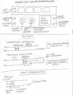
Re: Roberts/Akai mod instructions
OK, this is basically what I'm working from. I have a JBL input transformer (600ohm/50Kohm) for the balanced mic input and a suitable Jensen transformer for the balanced ouput, plus the 500ohm resistor and an Alps Blue Velvet potentiometer. I'm startiung to understand what you are saying, but I was confused by the requirements for additional capacitors and resistors on the signal ground lines etc.
OK, this is basically what I'm working from. I have a JBL input transformer (600ohm/50Kohm) for the balanced mic input and a suitable Jensen transformer for the balanced ouput, plus the 500ohm resistor and an Alps Blue Velvet potentiometer. I'm startiung to understand what you are saying, but I was confused by the requirements for additional capacitors and resistors on the signal ground lines etc.
Attachments
Grounded..
So... Let me get this straight..ALL "Grounds" need to be tied together (1)'Earth'(Green wire from input wall cord, tied to chassis immediatly entering chassis.(2) Power supply ground (Negative polarity of associated Caps), (3) Circuit "Ground/ Common" EG Grid leak resistors.
All three are suppose to have a 'Common' starting point as in when the green power comes into the chassis?
If that is so then whats' up with the all-in-one ground by solely using the chassis for everything?
I'm getting the impression that grounding is a black art that needs experimentation to work at its' best (Least hum)....is that the crux of the situation?
______________________________________Rick...........
No, no black art, it really is straightforward. Safety ground to the chassis from the power connector. Power supply and signal common tied together at one point. The only unknown is whether or not to tie that power supply/signal common directly to the chassis or not. Try it that way first, picking a point near the input. If there's no hum, you're done. If there is, lift that point away from the chassis and connect it back through a small (10-33 ohm) resistor.
A really good worked example is shown at the Aiken site using a Vox guitar amp.
A really good worked example is shown at the Aiken site using a Vox guitar amp.
SY said:If there is, lift that point away from the chassis and connect it back through a small (10-33 ohm) resistor...
...in series with a 0.01uF capacitor.
se
- Status
- This old topic is closed. If you want to reopen this topic, contact a moderator using the "Report Post" button.
- Home
- Amplifiers
- Tubes / Valves
- Ground questions