I have an amplifier with n°2 12AT7WA, n°2 12AU7 e n°4 KT88-98 tubes.
I changed all the tubes (leaving the KT88s) with NOS by Mullard.
I would like to improve the sound of this amplifier.
Any idea?
Schematic
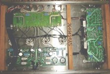
Picture 1
Picture 2
Thank you
p.s.: I think that the schematic in the manual is incorrect....but i'm not sure...i'm a NEWBIE
I changed all the tubes (leaving the KT88s) with NOS by Mullard.
I would like to improve the sound of this amplifier.
Any idea?
Schematic
Picture 1
Picture 2
Thank you
p.s.: I think that the schematic in the manual is incorrect....but i'm not sure...i'm a NEWBIE
I see a good number of 4007 SS diodes in the schematic. If, as I suspect, they are 1N4007s, replacing them with UF4007s will lower the noise level in the amp.
Mullard made tubes in both small signal slots might make the sound too "round". My taste runs towards a mix of Mullard and RCA, as midrange accent is combined with "chime".")
Mullard made tubes in both small signal slots might make the sound too "round". My taste runs towards a mix of Mullard and RCA, as midrange accent is combined with "chime".
leimaster,
Short of major surgery there is not a lot that can be done with this amplifier. Dashed this off in a hurry during my lunch break. I hope it is of some help.
I would start by purchasing a bag of 0.1uF/400V polypropylene Film/Foil capacitors and;
1) replace C1, C3, C11, C13, with the new caps - DON"T be tempted to make these caps larger in value. The circuit is "Williamson-ish" and the common problem with Williamson Designs is low frequency stability. Making these caps bigger WILL make any low frequency stability problem worse - don't do it
Also check the voltage across C23 and if less than 400V replace it too. Note the schematic says 0.22uF/250V that MUST be a "typo", there will certainly be more than 250V across it. If you can get a good 0.22uF Polypropylene cap of sufficeient voltage rating then replace C23, Also replace C15
2) add new (O.1uF/400V PP) caps across C5, C7, C39
3) Disable the Triode pentode Switch such that its in Triode Mode permanently. This should give better bass which is likely to be a little weak due to cascaded 15.9Hz roll offs (C1 and R23 followed by C11 and R29) - See comments at 1) above - leave those corner frequencies as is.
4) Add voltage balance resistors of 220K 1W across:
C19, C21, C35, C29, C25, C27 and the first 2 caps in the KT88 HV supply which are'nt marked.
5) replace 14 off 1N4007 with UF4007 or similar Ultrafast Soft Recovery Diodes.
Thats the end of the easy stuff - mayby stop at that and have a good listen.
Then if you really feel you must you could try:
5) Redo the bias circuit such that you have separate bias set pots for each KT88 - that is split the bottom (A side) of R29 and R31 to separate bias adjust pots (this will also require duplicating C9). These final bias filter caps could also have 0.1uF PP caps added across them.
6) Remove R27. replace with a current source wired from the common cathodes to the negative bias supply at R53/C39 junction.
Cheers,
Ian
Hi.
The schematic in the manual is incorrect.
Look at the trimmers on the psu board. There are 6.
4 are biastrimmers for the kt88.
Look at r 41=10 ohm
It sits on the switch board label r4=20ohm.
I have the same amp.
Start with biastrim.
Disable the Triode pentode Switch
The reley is shown with power on so You have to solder the 4 resistors off the switch print and connect direct to the tube (r37/r39).
I am very happy with mine, but i need a schematic. (the reel one)
And thanks Ian, i will try som off yours stuff.
Best Regards
Soren
Thank you for the answers.
Please don't laugh
Could it be possible that this version of the amplifier have separeted bias for every KT88?
to Ian:
a) why I need to use this small caps across the bigger?
b) Replace the 12AU7 driver tube with an ECC99 have an electrical reason or it's just because their sound is better?
to Soren:
a) I asked to the shop the right schematics. If I find it ... you find too
b) this is a pic of the bottom of the (maybe) switch side pic.
What did u do to disable the Triode pentode Switch?
A big thanks again.
You are driving me in passion.
Do not let the lack of an accurate schematics stop you.
Tracing a diagram from the actual amp is a good learning experience.
Looks like the 51 ohm (or whatever they may be) resistors are labelled R9,10,11,12 on the circuit board.
The 2.7K resistor could be instead of the 2 x 5.6K shown on the diagram.
SveinB.
Tracing a diagram from the actual amp is a good learning experience.
Looks like the 51 ohm (or whatever they may be) resistors are labelled R9,10,11,12 on the circuit board.
The 2.7K resistor could be instead of the 2 x 5.6K shown on the diagram.
SveinB.
I suggest that you do not rush the bypass of the triode swith until you are certain you only want to run triode mode.
In the meantime build your own opinion of triode and penthode sound.
Electrically it should make no difference if you have a switch or hard wired triode mode.
SveinB.
In the meantime build your own opinion of triode and penthode sound.
Electrically it should make no difference if you have a switch or hard wired triode mode.
SveinB.
gingertube said:I would start by purchasing a bag of 0.1uF/400V polypropylene Film/Foil capacitors and;
1) replace C1, C3, C11, C13, with the new caps - DON"T be tempted to make these caps larger in value. The circuit is "Williamson-ish" and the common problem with Williamson Designs is low frequency stability. Making these caps bigger WILL make any low frequency stability problem worse - don't do it
The problem with the Williamson design was due to clustering of time constants AND negative feedback. I cant see any NFB in this design so low frequency stability should be OK regardless of the values of the capacitors.
Jan E Veiset
Nightmare perpetrated...
I think this amplifier was intended to have negative feedback but whoever drew the diagram forgot to connect the 0 Ohm tap of the output transformer to ground.
I have to say, it all looks rather nastily derived.
1) R23 and R25 are far too low (470k or 1M) would be better. As has been said, if the feedback is implemented, the circuit may well have LF instability due to the clustering of coupling time constants - making R23 and R25 1M will assist in distancing them.
2) The HT electrolytics do not have resistors across them to ensure that they each have equal voltage across them. One example (there are many) is C19 and C21. Add a 220k 2W resistor across each capacitor.
3) Where are the grid stopper resistors on the KT88? Each KT88 should have a 1k (or so) resistor in series with the grid, soldered with the resistor body as close to the grid pin as possible to prevent RF instability.
4) There appears to be no HF compensation to account for output transformer. The 10kHz square wave response would need to be checked to determine values. Have a look at the original Williamson circuit to see where the small RC networks are added.
All in all, I'd say this was perpetrated by a semiconductor designer with little or no understanding of valves. Nevertheless, with a little work it could be made to be much better.
After i adjust the bias (4 trimmers - 2 left and 2 right on the psu board -- adjust to 1.1 v over the 20 ohm resisters on the switchboard) and resolder the resistors to leave out the triode/pentode switch.
A differnt animal all together.
But beware, i can see, that the layout on your switchboard is different
from mine.
I will send a picture when i get a reziser.
/Soren
A differnt animal all together.
But beware, i can see, that the layout on your switchboard is different
from mine.
I will send a picture when i get a reziser.
/Soren
- Status
- This old topic is closed. If you want to reopen this topic, contact a moderator using the "Report Post" button.
- Home
- Amplifiers
- Tubes / Valves
- Help! Upgrade a Music Angel KT88