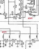
I was helping a friend to check out the HV value at various points of an old tube amp according to the accompanied schematics. What we found was that the voltage at the plate of the PP output tubes during operation was signifcantly lower than the values shown (~330V vs 430V). If one unplug the output tubes, then the HVs read about right (~430V). It appeared that even though the HV was above 400V at the beginning, it went down once the output tubes conducted, as it should. The schematic does not specify whether the values should be measured with the tubes out or in. Do anyone know what is the general practice (ie, tubes in or out) of manufacturers (McIntosh in this case) in the past when measured voltages are shown explicitly in their schematics? The amp works as is, but we are concerned that it may not be running at the designed operating point at all. TIA.
Attachments
In many cases it is not unusual for voltages to vary 5 - 10% from that stated on the schematic particularly in stages with relatively high value plate load resistors, meters of the day were rarely over 20K per volt so they loaded the circuit.
Tubes in, in all cases unless specifically noted otherwise!
Also not a good idea to run amps without their output tubes on full line voltage as a properly functioning supply, particularly if ss rectifier may over voltage components when unloaded.
In the output stage of an amplifier circuit the resistances tend to be small so even vintage meters aren't that significant a load on the circuit . This problem is more or less absent with modern digital meters which general have very high input impedances.
In this case there are two likely problem sources (assuming the tubes themselves are ok):
1. The output stage is drawing excessive plate current due bad coupling caps or bias supply.
2. The power supply capacitors are bad and have developed high enough esr to degrade supply regulation under load.
Coupling caps and electrolytics should be replaced in most vintage amplifiers at this point in time as 40 - 50 yr caps are generally ticking time bombs waiting to fail. (This applies to all paper, most electrolytic, and some very few early film types.)
kevinkr said:Tubes in, in all cases unless specifically noted otherwise!
That is what I had thought too.
Also not a good idea to run amps without their output tubes on full line voltage as a properly functioning supply, particularly if ss rectifier may over voltage components when unloaded.
Thank you for the reminder.
Coupling caps and electrolytics should be replaced in most vintage amplifiers at this point in time as 40 - 50 yr caps are generally ticking time bombs waiting to fail. (This applies to all paper, most electrolytic, and some very few early film types.)
I do have a heathkit cap tester. Is there a trick to do state-of-health checks of the filtering caps without desoldering?
Even if they appear healthy now, as Kevin says, they're like ticking time-bombs and should be replaced. You really don't want to wait until they fail.Is there a trick to do state-of-health checks of the filtering caps without desoldering?
I recommend blanket replacement of all supply electrolytics (cya thing) however it is pretty easy to tell with a meter and oscilloscope whether or not a cap is good. Just look at the ripple on the supply and the average dc level. If the dc level under load is within about 10% of the schematic value at the specified line voltage and load (use a variac) and the ripple is a few Vpk-pk (~ <10Vpk-pk) you're probably ok, if OTOH it reads much lower and you see a lot of ripple (say 100Vpk-pk) this is a sign of a very bad cap. Another good clue is if it seems to heat up very rapidly. (i.e. hot when its immediate surroundings aren't)
IMO it's just a no brainer to just replace these caps now, you'll come to regret not doing it if the almost unobtainium power transformer self destructs due to excessive current in the supply capacitors or one of the them explodes and/or burns whether or not the transformer fails.
Some stereo MAC amplifiers use solid state voltage doubling supplies, and the caps in these lead a very hard life. (IIRC 225, 240) If one of these develops a short or worse a partial short there is a real possibility that the power transformer may fail as well.
- Status
- This old topic is closed. If you want to reopen this topic, contact a moderator using the "Report Post" button.