Hi,
A few months ago there was some "talk" on Frank's 6SN7 tube preamp.
It was a typical two stage common cathode, cap coupled to a line driver.
Why not direct coupling, inistead of cap coupling?
I beleive someone suggested this, but not sure of out-come....does anyone recall?
Thanks,
Charlie T.
A few months ago there was some "talk" on Frank's 6SN7 tube preamp.
It was a typical two stage common cathode, cap coupled to a line driver.
Why not direct coupling, inistead of cap coupling?
I beleive someone suggested this, but not sure of out-come....does anyone recall?
Thanks,
Charlie T.

burnedfingers said:Why try to re invent the wheel?
Because it ought to sound better without that unneeded coupling capacitor and those extra resistors. Isn’t reinventing part of DIY?
Actually the direct-coupled cathode follower is as old as the hills. The only possible downside I can think of is stressing the grid of the CF at start-up and shut-down with rapid response SS power supplies. This situation varies greatly depending on power supply characteristics. But the 6SN7 is pretty beefy. With 6DJ8 CFs you will sometimes see a SS diode across the grid-cathode for protection. I think this should be avoided since the reverse-biased capacitance of diodes is non-linear. I always prefer gradual start-up supplies anyway (the B+ starting a few seconds after heater power was applied) .
Well Brian I have built both and listened to both and had others listen to both. The results were that the listeners liked the line stage with the coupling cap better. Now, there are those that would disagree such as you and say that the cap influences the sound. I don't think so in this case.
We could discuss the sonics pro and con of both the SS and tube rectification also and that is also part of DIY.
I have VR tubes for each channel in my line stage and that also has a sonic effect in my opinion.
What I meant by with my trying to re invent the wheel comment is that Frank's circuit is a proven one that many here have built.
Yes, he did post a direct coupled circuit for those that believe in the vodoo of capacitors. I've gotten a number of emails from members on this board about Frank's line stage and some like me have tried both and seem to favor the cap version.
Well, I can't and I won't argue about what you heard or prefer. If I'd sat next to you at your listening tests, I might even have agreed with your perceptions. But as general advice for this kind of circuit with dozens of other variables, I don't see your specific listening trial and preference as any kind of as general vindication for adding those extra parts. I have not built both these circuits exactly as drawn and have not therefore compared them as you have, although I have built numerous 6SN7 stages before, including cathode followers. So feel free to discount anything I say.
In a general sense, at best the additional cap will do little harm. It might add a tinge of flavor that that you like or is compensatory for some other existing sonic character elsewhere (and please don't get defensive; all our systems have characters that can be unwittingly compensated for). It's like seasoning a soup. But my soup stock might be different than yours. Not better or worse necessarily, just different.
It's just that it’s hard to argue in any universal sense that adding additional and technically unneeded components will make a design necessarily better. With duly noted exceptions, additional "unneeded" parts usually will only introduce new "distortions" that are not good: phase shift, dielectric hysteresis, noise, inductance. At worst, with a bad cap (which I'm quite sure you avoided), the results could be significantly worse. I don’t know what to make of your “voodoo” comment about caps. If you don’t think that coupling caps can sound different from one another, then there is probably little I can do to convince you otherwise.
An idea if you are so inclined: Cathode followers, being based upon 100% local feedback, can be subtly affected by reactive loading on the cathode (say, from cables). Even when well short of outright oscillation, I think this may explain why so many people diss the CF. If you can, try the direct-coupling option, but add a grid stopper to the CF. Vary to taste. You may also add a decoupling resistor in series with the output - say 100 ohms to 500 ohms. This will keep the cathode follower's feedback mechanism somewhat isolated from cable reactances. Perhaps your added coupling cap had just enough of the right impedance at high frequencies to damp incipient phase-margin problems in the CF. If that’s the case, direct-coupling with appropriate grid and cathode stoppers, might (note that I said only “might”) sound better to you than using the coupling cap and added bootstrapping resistors.
It will invert the signal. It is said that some people can hear the difference on some signals.
The direct-coupled version (see post 3) claims to run 7.15mA in the CF, but that is not possible with a 47k resistor run from a 250V supply.
The comment about input cap and resistor being omitted with a step attenuator assumes, of course, that the switch is make-before-break and that the valve has no grid current to create clicks. I would argue that the cap is needed more with a switch than a normal pot!
Coupling cap here does not hurt. Where it is better to take off the cap, before control grid of an output tube of a power amp, since it's dynamic resistance is non-linear. Here it is absolutely negligible compared to grid leak resistor's value, and grid current is small, stable, and linear. If the cap allows to balance both stages better, let it be.
Hello,
just a quick question on the DC coupled version of the preamp.
I built the cap coupled version and wish to convert it to a DC coupled type. I am going to replace the cathode resistor of the first stage with the 47K resistor. I was just wondering what value cap I would need to use for my output connection.
Ohm law puts my cathode at + 329v. Correct? This means I need a 400v cap rating: a very large cap!
How come every preamp I see on the web lacks that type of capacitor? Is everyone running a cap coupled version?
Sorry for the dumb questions.
Best,
Did you build the cap-coupled version from this schematic?
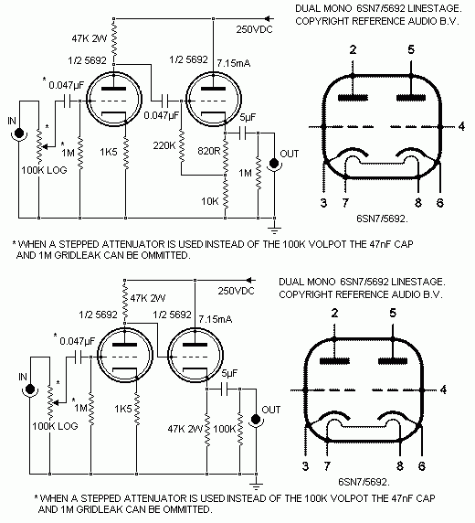
I think that figure of 7.15mA is for both stages combined. It's in a confusing place on the schematic. I think it might not be accurate, though. LTspice predicts 5.4mA current draw for the two stages combined (about 2.7mA per triode) with a +250V B+. If the B+ is increased to +330V, then the two stages combined draw 7.15mA.
Since the B+ is +250V, you probably want to use 300WVDC rated caps at a minimum. 400WVDC would be fine.
Which cap is the one you don't see in other schematics? Do you mean the input cap (0.047uF)?
--
Thank you Rongon,
as I suspected the current draw is less. Good to know!
What I meant to say is that I would've expected to see large caps mounted on the chassis of DC coupled versions of this preamp. Since I have seen none I figured I might be missing something. It wasn't a very strong or intelligent argument")
I built the DC coupled version because I wanted to see if I can get rid of some distortion. I love cap-less circuits and this seems a good candidate. I suspect, however, that the distortion is oscillation-induced.
In that regards, I see no grid stoppers which is odd. Maybe 1k grid stopper throughout might help.
Also, how critical is the value of the output cap? I have 3uf or 12uf caps (the 12uf caps being on the "large" side). Any suggestions there?
Thanks!
as I suspected the current draw is less. Good to know!
What I meant to say is that I would've expected to see large caps mounted on the chassis of DC coupled versions of this preamp. Since I have seen none I figured I might be missing something. It wasn't a very strong or intelligent argument
I built the DC coupled version because I wanted to see if I can get rid of some distortion. I love cap-less circuits and this seems a good candidate. I suspect, however, that the distortion is oscillation-induced.
In that regards, I see no grid stoppers which is odd. Maybe 1k grid stopper throughout might help.
Also, how critical is the value of the output cap? I have 3uf or 12uf caps (the 12uf caps being on the "large" side). Any suggestions there?
Thanks!
- Status
- This old topic is closed. If you want to reopen this topic, contact a moderator using the "Report Post" button.
- Home
- Amplifiers
- Tubes / Valves
- Frrank's 6Sn7 preamp...take out coupling cap??