Hi all,
I'm ready to build this HV regulated supply that now simulating OK, please comment ! I'm not that familiar with zener or regulated supply building.
Here some details:
- The transformer is salvaged from a >50W "steelphon" mixer, this transformer have 2 HV winding, nice, as I plan 2 HV slices.
After some calculations with resistance vs. permissible current chart, I think that windinds would be close to:
HV1= R30.8ohms / 332VAC@open ---PREV---> 420VDC@170mA MAX
HV2= R28.5ohms / 258VAC@open ---PREV---> 340VDC@150mA MAX
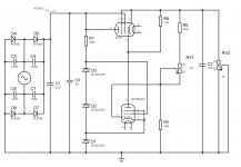
The schematic represents one slice, ground is here for simulation purpose and the whole thing should be floating with HV+ & HV- rails the 2 slices are able of serie connection for summing voltage (each slice having its own floating AC filament supply from another Xformer).
The supply is planned to deliver 100mA MAX.
* For HV1 slice all zeners are 39V 1W
* For HV2 slice all zeners are 33V 1W
* The series zener 330k res is 2W
* RV1 controls Output Voltage (RV2 is a test load for simulation)
So here comes the first question: Am I to optimistic about EL34 Power dissipation rating ? (the simulated supply goes down to ~100VDC@100mA)
What's the best way to limit current to a 100mA MAX ? (to protect the EL34,)
Anything wrong with the zeners ? It's the first time I design with them.
Any comment is welcome.
Best regards.
I'm ready to build this HV regulated supply that now simulating OK, please comment ! I'm not that familiar with zener or regulated supply building.
Here some details:
- The transformer is salvaged from a >50W "steelphon" mixer, this transformer have 2 HV winding, nice, as I plan 2 HV slices.
After some calculations with resistance vs. permissible current chart, I think that windinds would be close to:
HV1= R30.8ohms / 332VAC@open ---PREV---> 420VDC@170mA MAX
HV2= R28.5ohms / 258VAC@open ---PREV---> 340VDC@150mA MAX
The schematic represents one slice, ground is here for simulation purpose and the whole thing should be floating with HV+ & HV- rails the 2 slices are able of serie connection for summing voltage (each slice having its own floating AC filament supply from another Xformer).
The supply is planned to deliver 100mA MAX.
* For HV1 slice all zeners are 39V 1W
* For HV2 slice all zeners are 33V 1W
* The series zener 330k res is 2W
* RV1 controls Output Voltage (RV2 is a test load for simulation)
So here comes the first question: Am I to optimistic about EL34 Power dissipation rating ? (the simulated supply goes down to ~100VDC@100mA)
What's the best way to limit current to a 100mA MAX ? (to protect the EL34,)
Anything wrong with the zeners ? It's the first time I design with them.
Any comment is welcome.
Best regards.
Attachments
Hi Bembel,
The EL34 should be pretty forgiving of momentary overloads, just make sure that at the lowest design output voltage you are not over dissipating the tube - if necessary you can derate the output current at low voltages as necessary to stay inside the safe dissipation limits or you can simply add a second one in parallel.
Note that I have had problems with oscillating EL34/EL84 and strongly recommend a 0.01uF/1KV ceramic cap from the screen right to the chassis at the tube socket.
Grid stopper resistors of 1K - 10K right at the EL34 pin5 is a good idea too. You might want to do the same on both the screen grid and control grid of the error amplifier pentode as well.
I'm not sure about the zener voltages and you need to make sure that under no conditions does the screen hog the plate current in the error amplifier. I'd recommend a resistive divider.
Bypassing the zeners with small caps to deal with their considerable high frequency noise is recommended.
Add a fuse for gross faults and you should be ok.
There's an old trick for limiting dissipation through a single series pass tube of bridging it with an appropriate sized wire wound resistor. Some of the current will flow through it, but not enough to affect the regulating action of the tube.
Also, to reduce hum from the output you can try a small capacitor (.01ufd or more) from the EL34 cathode to the 6AU6 G1. This adds a little AC feedback to cancel it out.
Victor
Also, to reduce hum from the output you can try a small capacitor (.01ufd or more) from the EL34 cathode to the 6AU6 G1. This adds a little AC feedback to cancel it out.
Victor
I think maybe R6 should go to the EL34 plate, not its cathode.
I also think it would be better to use a much higher voltage zener (maybe 2 in series) in place of D1, to protect the 6AU6 from excessive plate-cathode voltage but be careful because that tube has a mx. heater-cathode voltage of only 90v.
As stated, bypass the zeners with 10uF caps and use stoppers to EL34 and 6AU6 screen and control grids.
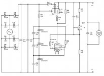
rev2
Thanks a lot, all, for your replies, here is rev2 ...
Now in the order:
is is that safe ? (it's ment to be bench floating supply)
more on this at the end ...
Why not from screen to cathode then ?
Sure good idea, thanks. Maybe we can lessen the value ? why not 100R-1k any drawbacks ?
I'm sorry for my limited english or american ? I don't understand what can be a "screen hog" (a pig in the story ? ;-) can you explain much please.
thanks
oops, I don't put them in the simulator. Sure.
You mean between A & K ? what's the way to calculate ? (//Ra&Rshunt ?). It's seems very interesting to me !
Thanks Victor
Hi Ray,
in fact I modified to my needs and transformer a schematic from very nice Mr Pierre Genet (---> http://cfp.radio.free.fr/index.html) and R6 clearly seats here (seems like logic to me, and simulate fine) but what the idea ? a "controled diode" ?
I don't follow you neither Ray, Va-k is still held by D2-D3=78V (nothing to see with D1 witch holds HT-toK ) ???
Sure, near obvious ... But isn't it a too big value ? I would have think (arghh my english !) at first of a small value like Kevin suggested ?
And then why not had a cap across ?
Thanks again for all of your inputs.
PS: I've surely not been that clear, THESES SUPPLIES are ment to be 2 FLOATING ONES able to be "stacked" to sum their voltages. They are not grounded to the chassis except the core of the HV transformer and an internal shield inside !
They have not exactly the same voltage (salvaged transformer, separate HV windings)
Concerning the FILAMENTS their AC supply come from another transformer (toroidal/2*6V) and each winding is feeding his HV slice (el34+EF94) thus the whole thing is floating
Thanks a lot, all, for your replies, here is rev2 ...
Now in the order:
kevinkr said:
Note that I have had problems with oscillating EL34/EL84 and strongly recommend a 0.01uF/1KV ceramic cap from the screen right to the chassis at the tube socket.
is is that safe ? (it's ment to be bench floating supply)
more on this at the end ...
Why not from screen to cathode then ?
Grid stopper resistors of 1K - 10K right at the EL34 pin5 is a good idea too. You might want to do the same on both the screen grid and control grid of the error amplifier pentode as well.
Sure good idea, thanks. Maybe we can lessen the value ? why not 100R-1k any drawbacks ?
I'm not sure about the zener voltages and you need to make sure that under no conditions does the screen hog the plate current in the error amplifier. I'd recommend a resistive divider.
I'm sorry for my limited english or american ? I don't understand what can be a "screen hog" (a pig in the story ? ;-) can you explain much please.
Bypassing the zeners with small caps to deal with their considerable high frequency noise is recommended.
thanks
Add a fuse for gross faults and you should be ok.
oops, I don't put them in the simulator. Sure.
HollowState said:There's an old trick for limiting dissipation through a single series pass tube of bridging it with an appropriate sized wire wound resistor. Some of the current will flow through it, but not enough to affect the regulating action of the tube
You mean between A & K ? what's the way to calculate ? (//Ra&Rshunt ?). It's seems very interesting to me !
Also, to reduce hum from the output you can try a small capacitor (.01ufd or more) from the EL34 cathode to the 6AU6 G1. This adds a little AC feedback to cancel it out.
Thanks Victor
ray_moth said:I think maybe R6 should go to the EL34 plate, not its cathode.
Hi Ray,
in fact I modified to my needs and transformer a schematic from very nice Mr Pierre Genet (---> http://cfp.radio.free.fr/index.html) and R6 clearly seats here (seems like logic to me, and simulate fine) but what the idea ? a "controled diode" ?
I also think it would be better to use a much higher voltage zener (maybe 2 in series) in place of D1, to protect the 6AU6 from excessive plate-cathode voltage but be careful because that tube has a mx. heater-cathode voltage of only 90v.
I don't follow you neither Ray, Va-k is still held by D2-D3=78V (nothing to see with D1 witch holds HT-toK ) ???
As stated, bypass the zeners with 10uF caps and use stoppers to EL34 and 6AU6 screen and control grids.
Sure, near obvious
... But isn't it a too big value ? I would have think (arghh my english !) at first of a small value like Kevin suggested ?And then why not had a cap across ?
Thanks again for all of your inputs.
PS: I've surely not been that clear, THESES SUPPLIES are ment to be 2 FLOATING ONES able to be "stacked" to sum their voltages. They are not grounded to the chassis except the core of the HV transformer and an internal shield inside !
They have not exactly the same voltage (salvaged transformer, separate HV windings)
Concerning the FILAMENTS their AC supply come from another transformer (toroidal/2*6V) and each winding is feeding his HV slice (el34+EF94) thus the whole thing is floating
Attachments
oOps
For screens indeed !
Across R1 !
Sorry didn't had the time to edit.
Maybe we can lessen the value ? why not 100R-1k any drawbacks
For screens indeed !
And then why not had a cap across ?
Across R1 !
Sorry didn't had the time to edit.
In regards to the screen bypass (0.01uF/1KV ceramic) if the whole supply will float return the cap directly to the supply return and make the connections as short as possible. Don't use a film cap here as they tend to be too inductive.
Smaller grid stopper resistance values don't always work, particularly if you use mf resistors.
Hogging current just means that the current is going to an unintended place - in this case to the screen instead of the plate of your error amplifier tube. This can happen if the voltage on the screen is significantly higher than the plate voltage. Depending on the accuracy of your pentode tube model and how you look at screen current this may or may not show up in your simulations.
Hi bembel,
The way I suggest is what I'm used to seeing. Your way (M. Genet's way) might work, I don't know. That is why I said "I think maybe" rather than stating it as a fact. You might find it useful to see what Steve Bench has to say on error amplifiers. In his schematics, you will see that the error amplifier plate load resistor (R6 in your case) goes to the series tube plate, not the cathode.
The combination of zeners D2 and D3 will hold the screen-cathode voltage of the 6AU6 at 78v but will not limit the plate-to-cathode voltage. My suggestion here (which should be taken in combination with my suggestion about R6) is to elevate the cathode voltage of the 6AU6, so that plate-to-cathode voltage will be less likely to exceed the limit for that tube. This is just a safety precaution, in case unexpected conditions in your circuit could cause the error amplifier to be exposed to the full output voltage of your rectifier.
modified to my needs and transformer a schematic from very nice Mr Pierre Genet (---> http://cfp.radio.free.fr/index.html) and R6 clearly seats here (seems like logic to me, and simulate fine) but what the idea ? a "controled diode" ?
The way I suggest is what I'm used to seeing. Your way (M. Genet's way) might work, I don't know. That is why I said "I think maybe" rather than stating it as a fact. You might find it useful to see what Steve Bench has to say on error amplifiers. In his schematics, you will see that the error amplifier plate load resistor (R6 in your case) goes to the series tube plate, not the cathode.
I don't follow you neither Ray, Va-k is still held by D2-D3=78V (nothing to see with D1 witch holds HT-toK ) ???
The combination of zeners D2 and D3 will hold the screen-cathode voltage of the 6AU6 at 78v but will not limit the plate-to-cathode voltage. My suggestion here (which should be taken in combination with my suggestion about R6) is to elevate the cathode voltage of the 6AU6, so that plate-to-cathode voltage will be less likely to exceed the limit for that tube. This is just a safety precaution, in case unexpected conditions in your circuit could cause the error amplifier to be exposed to the full output voltage of your rectifier.
Sorry to be so long for reply. I was busy and will be busy next week again.
Thanks Ray for steve's link, I have to take time read and understand it now. I'm sorry for my confusion with D1-D2-D3, I was tired very then !
Thanks Kevin for your precision with the cap.
More to come in a few days ...
Thanks Ray for steve's link, I have to take time read and understand it now. I'm sorry for my confusion with D1-D2-D3, I was tired very then !
Thanks Kevin for your precision with the cap.
More to come in a few days ...
- Status
- This old topic is closed. If you want to reopen this topic, contact a moderator using the "Report Post" button.
- Home
- Amplifiers
- Tubes / Valves
- HV supply please comment before building