Do I need a Trafo for the HV in my 12au7 (ECC82)?
Sorry if this is a dumb question, but I am just getting into tubes... so here is my dumb question")
I live in Europe, and have 220V 50Hz mains. Can I just rectify this and run it straight to the HV on my ECC82 tubes or do I really need a Transformer to feed the plates? I am going to run 2 tubes in a CE setup for a simple buffer to some inverted LM4780 and would love to not have to find a X-former for it.
Will it blow a tube, will it brown out the city, do I need some inductance in there to feed the tubes? Can I just put in an inductor?
I searched quite a bit, and I see a X-former in EVERY tube PS I have seen (At least the ones that run high voltage...) and they all seem to be expensive to buy.
Thanks for any help.
Sorry if this is a dumb question, but I am just getting into tubes... so here is my dumb question
I live in Europe, and have 220V 50Hz mains. Can I just rectify this and run it straight to the HV on my ECC82 tubes or do I really need a Transformer to feed the plates? I am going to run 2 tubes in a CE setup for a simple buffer to some inverted LM4780 and would love to not have to find a X-former for it.
Will it blow a tube, will it brown out the city, do I need some inductance in there to feed the tubes? Can I just put in an inductor?
I searched quite a bit, and I see a X-former in EVERY tube PS I have seen (At least the ones that run high voltage...) and they all seem to be expensive to buy.
Thanks for any help.
DaMeat,
EC8010 is CORRECT. A direct connection to the AC mains is DEADLY DANGEROUS. Jrevillug's remark about an isolation trafo is spot on. The Triad N-68X has dual primaries, which make it suitable for use in both "120" V. and "240" zones. Bridge rectify for a "150" V. B+ rail. Use a "full wave" voltage doubler for a "300" V. B+ rail. At 50 VA, the N-68X can support a small power amp. It will be lightly stressed feeding a preamp. The Triad N-68X sells for about 11 USD. Figure on 10 Euros + VAT; hardly a "big ticket" item
EC8010 is CORRECT. A direct connection to the AC mains is DEADLY DANGEROUS. Jrevillug's remark about an isolation trafo is spot on. The Triad N-68X has dual primaries, which make it suitable for use in both "120" V. and "240" zones. Bridge rectify for a "150" V. B+ rail. Use a "full wave" voltage doubler for a "300" V. B+ rail. At 50 VA, the N-68X can support a small power amp. It will be lightly stressed feeding a preamp. The Triad N-68X sells for about 11 USD. Figure on 10 Euros + VAT; hardly a "big ticket" item
Re: Do I need a Trafo for the HV in my 12au7 (ECC82)?
Of course you can. However, you definitely SHOULD NOT. Yes, yes, yes, I know, it was done all the time back in the "good ol' days". Can you guarantee that it will always be plugged in so that the circuit neutral is connected to the mains neutral? No idgit ever miswired a wall socket? No one will ever use an extension cord with your gizmo? Your power company will never have a load imbalance that takes the AC neutral above ground potential? Never????? There was a reason that this particular topology was called a "suicide box".
Power xfmrs aren't cheap. However, they are much less expensive than the sound card/preamp/tape deck/CD player/etc that you will eventually ruin when you zap it with the full mains voltage. Even in the day, power xfmrless, low powered amps ruined lots of equipment. Guitar players who used these as "practice amps" often found it to be a most shocking experience.
DaMeat said:Sorry if this is a dumb question, but I am just getting into tubes... so here is my dumb question
I live in Europe, and have 220V 50Hz mains. Can I just rectify this and run it straight to the HV on my ECC82 tubes...
Of course you can. However, you definitely SHOULD NOT. Yes, yes, yes, I know, it was done all the time back in the "good ol' days". Can you guarantee that it will always be plugged in so that the circuit neutral is connected to the mains neutral? No idgit ever miswired a wall socket? No one will ever use an extension cord with your gizmo? Your power company will never have a load imbalance that takes the AC neutral above ground potential? Never????? There was a reason that this particular topology was called a "suicide box".
I searched quite a bit, and I see a X-former in EVERY tube PS I have seen (At least the ones that run high voltage...) and they all seem to be expensive to buy.
Thanks for any help.
Power xfmrs aren't cheap. However, they are much less expensive than the sound card/preamp/tape deck/CD player/etc that you will eventually ruin when you zap it with the full mains voltage. Even in the day, power xfmrless, low powered amps ruined lots of equipment. Guitar players who used these as "practice amps" often found it to be a most shocking experience.
Hi DaMeat
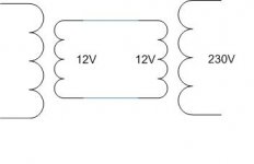
One thing you can do is connect to trafo back to back. I attached a small drawing illustrating it. One extreme you connect to the mains, while the other side you connect to the PSU. The 12V you may use for the filaments, feeding it straight to the filaments or maybe rectifying and regulating it.
www.dickbest.nl has some toroidal units 30VA for 8 euro's each. Go to the site, choose aanbiedingen en you can buy two pieces. I do not have connections with him, just buy some items now and then.
Good luck
Erik
Attachments
OK, I understand the concerns for an isolation X-Former now. Worried about chassis GND suddenly being 220V, ground loops, and DC offset.
I think I could take care of all those problems in my design but not worth the trouble. I'll scrounge a couple "standard" X-Formers and wire them up like ErikdeBest suggests.
BTW $10 is about all I'm spending so far on the whole amp, with sample chips and 2nd hand tubes so a "NEW" X-Former would be doubling my costs I'll get some used ones and keep my costs less than $15.
I think I could take care of all those problems in my design but not worth the trouble. I'll scrounge a couple "standard" X-Formers and wire them up like ErikdeBest suggests.
BTW $10 is about all I'm spending so far on the whole amp, with sample chips and 2nd hand tubes so a "NEW" X-Former would be doubling my costs
I'll get some used ones and keep my costs less than $15. Decided to resurect this thread as i have been wondering recently about dispensing with the power transformer to achieve an entirely transformerless amp. I was aware that most people said it was highly dangerous but I could not understand why or find answers that went beyond "ITS DANGEROUS" or saying things like:
I think 'why?' and then, 'can it be done safely?'
However having two kids + cats + partner who is none to keen on high voltage stuff in the house anyway, I thought i should figure it out for sure either way.
If this is such a dangerous idea there really should be a clear readily available explanation for anyone who is considering it. Maybe in the safety practices thread. (Although this is the last place I looked)
Bearing in mind I'm in the UK - my thought process was as follows:
If you start with the available rectifiers you either have half wave Voltage doubler or full wave bridge.
With a half wave rectifier, assuming everything is connected the right way and no DC potential between neutral and earth (a big and dangerous assumption, I know) you end up with your earth, a common at earth potential and rectified 240V line, (340V if feeding a cap). Fine. However If the previous assumptions were wrong you could end up with: Earth, a rectified line at near earth potential with whatever DC offset there may be and a common at 240V (340V) below this.
So why is this a problem? Well assuming your chassis is earthed and the circuit common isn't tied to ground anywhere within, the greatest danger is from the connection terminals (speaker / RCA etc). The common for these would then be several hundred volts away from earth. Even assuming no-one touches these it would nicely fry any other piece of equipment you connect.
I thought maybe you could have a small circuit to test which wire is neutral and then route the mains the opposite way if connected wrong, but the only way I can think of doing this is to test for current flow from (supposed) neutral to earth, but any current flowing to earth will trip the earth leakage breaker in the main fuse box and this will happen if there is any DC offset anyway. It might be possible to make this work but I gave up at that point.
With the voltage doubler you get 2 lines out symmetrically either side of neutral at +/- 340V, but with live and neautral the wrong way you get 2 lines that bounce up and down referenced to earth, the lower between 0V and -680V, the upper between 0 and +680V. Not very useful for all the above reasons and more.
That leaves the bridge. With this you get 2 rails symmetrically again at +/- 120V(170V) but as the live and neutral are treated the same by the rectifier it doesn't matter if they are the wrong way around. Now +/- 170V might not sound very useful but as I said- this is for a transformerless amp, needing symmetrical +/- lines for the output stage. so this would be ideal. The only problem I can see is the DC offset which could still potentially fry other equipment, but this could be avoided in part by 2 equal resistors in series across the rectifier output and then tying the center point (theoretical 0V) to earth. Any offset would then trip the earth leak breaker and stop any damage occuring (...and the use of any electricity in the house ). There is probably a better way...
I am still a bit of a newbie to audio electronics so PLEASE tell me If my thinking is way out, but to me this last solution seems reasonably safe.
As I said I have kids / pets etc... so I am careful, thinking carefully before trying anything. Judging by some posts I have read others are not so cautious and prefer to tinker and experiment rather than think. So in my view people need to be given more info than "IT'S DANGEROUS!"
without explaining why these things matter. I've never been the type of guy who just hears "It's dangerous" and thinks 'OK, I won't do it then'.Can you guarantee that it will always be plugged in so that the circuit neutral is connected to the mains neutral? No idgit ever miswired a wall socket? No one will ever use an extension cord with your gizmo? Your power company will never have a load imbalance that takes the AC neutral above ground potential?...
I think 'why?' and then, 'can it be done safely?'
However having two kids + cats + partner who is none to keen on high voltage stuff in the house anyway, I thought i should figure it out for sure either way.
If this is such a dangerous idea there really should be a clear readily available explanation for anyone who is considering it. Maybe in the safety practices thread. (Although this is the last place I looked)
Bearing in mind I'm in the UK - my thought process was as follows:
If you start with the available rectifiers you either have half wave Voltage doubler or full wave bridge.
With a half wave rectifier, assuming everything is connected the right way and no DC potential between neutral and earth (a big and dangerous assumption, I know) you end up with your earth, a common at earth potential and rectified 240V line, (340V if feeding a cap). Fine. However If the previous assumptions were wrong you could end up with: Earth, a rectified line at near earth potential with whatever DC offset there may be and a common at 240V (340V) below this.
So why is this a problem? Well assuming your chassis is earthed
and the circuit common isn't tied to ground anywhere within, the greatest danger is from the connection terminals (speaker / RCA etc). The common for these would then be several hundred volts away from earth. Even assuming no-one touches these it would nicely fry any other piece of equipment you connect. I thought maybe you could have a small circuit to test which wire is neutral and then route the mains the opposite way if connected wrong, but the only way I can think of doing this is to test for current flow from (supposed) neutral to earth, but any current flowing to earth will trip the earth leakage breaker in the main fuse box and this will happen if there is any DC offset anyway. It might be possible to make this work but I gave up at that point.
With the voltage doubler you get 2 lines out symmetrically either side of neutral at +/- 340V, but with live and neautral the wrong way you get 2 lines that bounce up and down referenced to earth, the lower between 0V and -680V, the upper between 0 and +680V. Not very useful for all the above reasons and more.
That leaves the bridge. With this you get 2 rails symmetrically again at +/- 120V(170V) but as the live and neutral are treated the same by the rectifier it doesn't matter if they are the wrong way around. Now +/- 170V might not sound very useful but as I said- this is for a transformerless amp, needing symmetrical +/- lines for the output stage. so this would be ideal. The only problem I can see is the DC offset which could still potentially fry other equipment, but this could be avoided in part by 2 equal resistors in series across the rectifier output and then tying the center point (theoretical 0V) to earth. Any offset would then trip the earth leak breaker and stop any damage occuring (...and the use of any electricity in the house
). There is probably a better way...I am still a bit of a newbie to audio electronics so PLEASE tell me If my thinking is way out, but to me this last solution seems reasonably safe.
As I said I have kids / pets etc... so I am careful, thinking carefully before trying anything. Judging by some posts I have read others are not so cautious and prefer to tinker and experiment rather than think. So in my view people need to be given more info than "IT'S DANGEROUS!"
Hi Stone T,
I thought Miles spelled it out pretty well in his response to the original poster.
Mistakes happen in house wiring all the time, deleting the transformer removes all circuit isolation from these sorts of errors resulting in the possibility of circuit common getting connected to the hot side of the mains. You never want the possibility of exposure to mains voltage if possible. Obviously high voltage supplies in tube/valve amps are lethal in their own right, but usually if a device malfunctions and suffers a catastrophic failure high current mains voltage won't normally appear on the outputs or chassis which with a single unfortunate coincidence could occur quite easily without a transformer. (It's as much about odds as anything, and without a transformer they aren't in your favor.)
Think of a transformer as your life insurance policy, with it few if any failures could be lethal to the end user, without it there is a distinct possibility that someone could be injured or killed if the ground connection you mention is absent on your receptacle or the hot and neutral are swapped. Both can happen, and I have found both instances in my own house - now all fixed.
Transformers have another big benefit which is not often mentioned (and probably rightfully so) in these discussions and that is the transformer's leakage inductance provides a fair measure of protection to components on the secondary side from lightening generated and network switching transients.
Note that regardless of what we all say about the advisability of this approach, your assurance (insurance in the US) company and local building inspector will take a dim view of this approach, particularly if you have an accident that results in injury or damage to property.
I am sure there is online literature somewhere that spells out the hazards clearly from BSA, TUV, UL or CSA. I'd read it..
I'd do some research into the consequences of this design choice and I think you'll be able to persuade yourself quite effectively of the ill-advisability of this move.
StoneT said:...
If you start with the available rectifiers you either have half wave Voltage doubler or full wave bridge.
With a half wave rectifier, assuming everything is connected the right way and no DC potential between neutral and earth (a big and dangerous assumption, I know) you end up with your earth, a common at earth potential and rectified 240V line, (340V if feeding a cap). Fine. However If the previous assumptions were wrong you could end up with: Earth, a rectified line at near earth potential with whatever DC offset there may be and a common at 240V (340V) below this.
So why is this a problem? Well assuming your chassis is earthed
And of course fry anyone who touches two chasis with a 340V DC potential difference.
I thought maybe you could have a small circuit to test which wire is neutral and then route the mains the opposite way if connected wrong
Wouldn't help anyway as there is always some difference between ground and neutral, which, if nothing else, will trip the differential safety switch for your mains.
That leaves the bridge. With this you get 2 rails symmetrically again at +/- 120V(170V)
Check again, you don't. You get one at 340DC and one close to neutral, by a diode drop. Again, your 0V is neither neutral nor ground and if connected accidentally will blow equipment.
In other words, you must use some form of galvani isolation, period. Either for the mains, or for all other signals (in the latter case everything on the enclosure must be isolated from the mains in any form, or isolated, period. Just think old tube TV sets with no mains transformer and series connected heaters. There is a reason they were wood or later plastic.
kevinkr said:I'd do some research into the consequences of this design choice and I think you'll be able to persuade yourself quite effectively of the ill-advisability of this move.
Or, as someone recently very eloquently put it: a transformer costs less than a coffin and a funeral.
ilimzn said:
Or, as someone recently very eloquently put it: a transformer costs less than a coffin and a funeral.
At the very least..
OK, I really should have done a bit more thinking about this before making that post.
Thanks everyone for the replies.
That's just the thing, he said there could be things wrong with the supply (which I was already aware of) but didn't say why these things matter.
To my mind if you have a bridge rectifier, both input terminals are treated the same and so it doesn't matter if they are reversed. and in that respect I was right.
OK, I did check again. I did a very quick spice sim to see what the output is.
Result: We are both wrong!
The attached image shows the outputs for resistive load and cap input respectively. My '0V point' is at ~120V ac either way.
Not very useful for connection to anything else!
It is therefore only possible to use the half wave rectifier which I fully understand is highly inadvisable.
One thing this has shown me is I had assumed like ilimzn that if you use a transformer and ground the lower output of the bridge rectifier, your 0v line is only a diode drop away from the lower rectifier input. So grounding one terminal of the transformer instead would only raise the common by the diode drop. This seems to be true for a resistive load but for cap input, grounding the transformer terminal would produce rectifier output as if the transformer wasn't there. You are basically making one terminal into a 'neutral'
I guess I'll be buying a HUGE isolating transformer for my OTL then.
Thanks everyone for the replies.
kevinkr said:
I thought Miles spelled it out pretty well in his response to the original poster.
That's just the thing, he said there could be things wrong with the supply (which I was already aware of) but didn't say why these things matter.
To my mind if you have a bridge rectifier, both input terminals are treated the same and so it doesn't matter if they are reversed. and in that respect I was right.
ilimzn said:
Check again, you don't. You get one at 340DC and one close to neutral, by a diode drop.
OK, I did check again.
I did a very quick spice sim to see what the output is.Result: We are both wrong!
The attached image shows the outputs for resistive load and cap input respectively. My '0V point' is at ~120V ac either way.
Not very useful for connection to anything else!
It is therefore only possible to use the half wave rectifier which I fully understand is highly inadvisable.
One thing this has shown me is I had assumed like ilimzn that if you use a transformer and ground the lower output of the bridge rectifier, your 0v line is only a diode drop away from the lower rectifier input. So grounding one terminal of the transformer instead would only raise the common by the diode drop. This seems to be true for a resistive load but for cap input, grounding the transformer terminal would produce rectifier output as if the transformer wasn't there. You are basically making one terminal into a 'neutral'
I guess I'll be buying a HUGE isolating transformer for my OTL then.
Attachments
- Status
- This old topic is closed. If you want to reopen this topic, contact a moderator using the "Report Post" button.
- Home
- Amplifiers
- Tubes / Valves
- Do I need a Trafo for the HV in my 12AU7 (ECC82)?