ray_moth said:
Afterthought: if you have a CCS in the tail of an LTP, there is no need to worry about the mu in each half being different. AC balance is assured, as long as the plate loads are identical. All you have to do is make sure the quiescent current through each triode is the same, which you can correct with resistors in the cathodes.
There is a downside to this. Broskie of Tubecad fame pointed out that with a fixed grid voltage the current will differ between the two halves in a differential circuit. He had a special on Blumlein's current balancing in differential output stages (21 May 2005). Also this might, I think, easily lead to drift.
The classical method is indeed, as you pointed out, to have a potmeter in the anode circuit (which of course in an ideal world is non-inductive and doesn't have any temparature effects...). But I suspect that this can result some distortion-spectrum differences.
I didn't say anodes, I said cathodes and I was talking about fixed resistors, not a pot. It doesn't need to be a pot, just having resistors there will improve the DC balance, just in case the two triodes arfe not perfectly mathced.
If you're using a CCS in the tail, balancing the loads with a pot is only necessary if the fixed resistors used for the plate loads are not well matched. If they are, then the CCS will ensure that the AC signal balance is perfect.
If you're using a CCS in the tail, balancing the loads with a pot is only necessary if the fixed resistors used for the plate loads are not well matched. If they are, then the CCS will ensure that the AC signal balance is perfect.
So if ">=" reads not worse than, then
(1) LTP+CCS >= (2) split-load (cathodyne) >= (3) LTP(passive)? So looks like (1) will be the next thing for me to play with. Thank you all.
When browsing Altec schematics posted on the web, found this asymmetric treatment (from 1568A, attached) of the coupling/blocking capactors following a 6cg7 split-load. What is the advantage of doing this?
Attachments
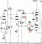
2004ex said:When browsing Altec schematics posted on the web, found this asymmetric treatment (from 1568A, attached) of the coupling/blocking capactors following a 6cg7 split-load. What is the advantage of doing this?
Probably phase compensation for stability with gNFB.
2004ex said:When browsing Altec schematics posted on the web, found this asymmetric treatment (from 1568A, attached) of the coupling/blocking capactors following a 6cg7 split-load. What is the advantage of doing this?
Notice that the bottom section of the PP 6CG7 is direct coupled to the cathode of the split-load tube through R8. C4 is not a coupling cap; as Miles said it appears to work in combination with R8 as a phase compensation network. The 1M R7 provides grid bias for the top section of the PP 6CG7 which is cap coupled to the plate of the split-load. Perhaps Altec decided that the compensation network is necessary because only one of the two sections is direct coupled. WTFDIK.
-- Dave
I should add, I'm not completely opposed to asymmetric PP drive just because it doesn't look good on paper.
I haven't heard one, but many people report that the Seth amp sounds very good. I do know (from conversations with someone that has probed a similar circuit) that the signals at the two PP grids of the Seth are FAR from symmetric. The top grid - which is really just cap coupled with a grid choke - looks very 'good' while the bottom grid - which is really just fed from an inverting interstage - shows all the expected frequency anomalies. Still, people say the amps sound fantastic.
Returning to the subject of this thread, I have built very good sounding PP amps with isodyne phase splitters (as found in the simple Magnavox amps.) This was some years ago when I was experimenting with PP EL84 amps. I found that the isodyne seemed to have more of the realism present in SE amps than the much more symmetric concertina and LTP.
-- Dave
Hi RayMoth ,
Sorry for the delaied reply , about your post # 18 ,
I don’t know how to calculate the gain of Scoyoc
phase inverter , too .
The only information I could get from the bibliography
is that the total gain of Scoyoc original design ( 6SN7
and 6SL7 ) is ~ 60 times . It’s very close to the “mu”
of a 6SL7 tube . May be the answer ??
Best Regards ,
Carlos
Hi Carlos,
Thanks for getting back. That figure of 60 looks about right for the gain of both sides of the splitter with unbypassed cathodes, which is what I thought.
Assuming for 6SL7:
Mu = 70
Internal plate resistance Rp = 45k
Plate load Rl = 120k
Cathode resistor Rk (unbypassed) = 1k
We would get, from each half of the 6SL7, a gain
= Rl * Mu / ((Rk * (Mu+1) + Rp + Rl)
= (120,000 * 70)/((1000*(70+1) + 45,000 + 120,000)
=35.59
Together with the cathode follower, we get a net gain
= 35.59 * 0.9
= 32
Since there are two halves to the splitter, both with roughly the same gain, the total gain = 64
Best regards,
Ray
P.S. Does anyone know of a phase splitter (or invertor, if you like) using tubes, where you don't lose at least half the gain?
refference said:Many applications
can easy tolerate the wide variation in output impedance
between the two signals”
Just a correction here (and this was not said by Refference; he quoted somebody else), if needed:
Contrary to superficial appearance, the output impedances of the two halves of the cathodyne are the same if the external load impedances are the same. Kirchoff's laws forces that - same current through both halves, etc.
Regards
Johan Potgieter said:
Kirchoff's laws forces that - same current through both halves, etc.
Regards
Johan- In the real world the beauty of tube circuits is massive working tolerance and everything still works and getting away with it ! Great but the case for fidelity and distortion is another. The Kirchoff law assumption holds fine so long one can discount Miller stage currents from the output or proceeding stages „going backwards“ upsetting the effective output impedance of earlier stages. When most tube stages (and tubes as such have large tolerances) operate at high Z the Miller effect isn’t insignifigant, and a thd analyser will show that most stages do have considerable distortion mismatches in earlier stages. One hopes the push pull output stage will cancel out the harmonics but only while the high freq loop gain holds up and the layout is balanced. (most arent‘). My assumptions are without global nfb. The formula used in calculating Mosfet gate drive slew rate current illustrates je higher the output stage voltage the greater effect the Miller effect. Same applies to tube stage grids.
If a push pull voltage driver stage stage is used to couple split-load phasesplitter to output stage and then Miller effects from output stage going „backwards“ to the input are largely isolated and the distortion waveform quality from both upper and lower outputs of the split-load phasesplitter are near similiar...this is not the case when each of the split-load phase-splitter outputs directly drives the output stage grids. The unsymmetrical impedance created by Miller effect highlights thd at high audio freqs.
Williamson had this sorted out, only in my designs using push-pull voltage drivers I use local feedback from common coupled cathode to grids. This improves the IMD and further balances the drive, obliviating the need for pots and adjustments.
Global nfb (at least 20dB for hi-fi) will correct for alot of Miller effect mistolerance
sofar while enough loop gain holds up. It’s all down to the o/p transformer.
The sound quality of a tube amplifier subjectly designed to have all thd „ ironed out“ in a perfect output stage is unrealistic. Global nfb does a wonderful job correcting alot of deficiency. I’m implying that for best bandwidth fidelity for tube HiFi, the use of parallel push-pull pairs with low B+ and high current is the optimum way forward. So for those who love high B+.....(ideal for MI) is a wonder how 845 and other high voltage users can claim excellent HiFi fidelity. On paper without a darned good driver ..doesn’t show it..
As for LTP .... any comments ?
richj
Here is what it is (Worthen article):
http://www.aikenamps.com/Isodyne.pdf
Usual comments about it are: too complicated, too many tubes, and it requires adjustment (which will need re-adjustment as the tubes age), assymmetrical (phase issues).
It's basically a Floating paraphase or See-saw splitter with some cathode followers put in before the grid feedback pickoff divider.
----------------------------------------------------------------
Something more interesting would be to put a CCS tailed LTP in place of the cathode followers of the Worthen version. This would guarantee equal output phases. The now full inverted inputs to the LTP would give it full Mu gain instead of the usual 1/2 Mu. The pickoff divider for the 1st stage grid could be put into the plates of the LTP, or, with some dual (one side tapped for pickoff) cathode resistors could come off the LTP tail (just like the Worthen then, but with full Mu gain outputs at the plates available and no balancing problem anymore) No need for a subsequent driver stage with all this gain. Could use triodes for the input stage (and LTP) to lower input noise, with so much gain available. Ageing of the tubes would only drop the full stage gain, but would still leave the phases equal (the LTP equalizes). (ie, no adjustments needed)
Getting it phase stable might be a problem (especially if the grid feedback comes off the LTP plates)........ Should be workable with the grid feedback coming off the altered LTP tail (with CCS midpoint, or looking at Fig. 5 in the Worthen article, the CCS could be put in at the true center point of the divider or something like the output stage grid biasing network could be used to attach the CCS to a psuedo center point of the divider, ie where the 100Ks meet to go to ground).
Edit:
Taking the grid feedback for the 1st stage from the LTP tail still leaves it sensitive to common mode swing there. Not sure if this presents a problem with tube ageing. CM swing might inject some 3rd H too. (need to simulate)
Last edited:
I was really hoping for a discussion of Isodyne phase splitters.
I have the original "white paper" on it from E. F. Worthen and it's dated "August, 1958". Worthen promises excellent balance from DC to "Channel 7", and provides sample schemos.
However, look at that date: 1958. Back in those days, they didn't have any decent solid state devices, and all transistors were very crude point contact devices. They were noisy, unreliable (if the things worked at all: they came in packages with stickers over holes that gave access to the points because you probably had to wiggle them around before the thing would work at all, and they were hideously expensive). ICs hadn't been thought of, so no CCS chips either.
Designs like the Isodyne and Van Soyoc existed to solve problems that are best solved these days with an active load in the tail of an LTP. That wasn't an option back then, so we had these overly complex, fussy, and potentially unstable phase splitters. Both the Isodyne and Van Soyoc require an o'scope to align them, for periodic realignments, and since the Van Soyoc required cross coupling, it was potentially an astable multibibrator waiting to happen.
Need DC to daylight balance in a phase splitter? A MOSFET-based "cathodyne" can do that easily. It could also be done with a pentode that had a floating screen supply, and was done for o'scope vertical deflection amps, good to 8.0MHz.
Unless you want it for some sort of nostalgia appeal, it ain't worth it these days. There are better alternatives if you're willing to sell your soul to the Solid State Devil.
With a little more thought, the idea of extending the Worthen Isodyne with an LTP in place of the CFs, is unnecessarily complicated.
Can achieve the same effective results by just using an LTP with a CCS tail and then a resistive divider between the plates to drive the undriven grid of the LTP. So one gets full Mu gain from the LTP tubes, and equal phases automatically. Tube ageing will reduce the overall gain, but not the phase splitting. Would be dangerous if tube gains could increase, since it could become an oscillator this way. (an issue with SS and a temperature increase, but safe for tubes which only go downhill.)
Equivalent to a floating paraphase with a CCS tail between the tubes.
Last edited:
Hey,
What I'm trying to do is come up with a new front end for my Dynaco Mark VI's. I need to swing about 150 volts to drive the four KT88's the amp now runs. Sy suggested the EF86 and Ecc83 from the mullard 5-20. But my friend, Rob Hull, at Tube Depot tells me non-micophonic EF86 don't exist. AFTER I ordered four Wnged C EF86 from Russia. I'm an amateur at design But the 12AX7 is the only triode I've found that can swing that kind of voltage. But to do so takes it into some really non-linear territory. If I could find out how much gain the LTP has I might have a better idea how much I would need to get out of the preamp tube.
What I'm trying to do is come up with a new front end for my Dynaco Mark VI's. I need to swing about 150 volts to drive the four KT88's the amp now runs. Sy suggested the EF86 and Ecc83 from the mullard 5-20. But my friend, Rob Hull, at Tube Depot tells me non-micophonic EF86 don't exist. AFTER I ordered four Wnged C EF86 from Russia. I'm an amateur at design But the 12AX7 is the only triode I've found that can swing that kind of voltage. But to do so takes it into some really non-linear territory. If I could find out how much gain the LTP has I might have a better idea how much I would need to get out of the preamp tube.
Hey,
What I'm trying to do is come up with a new front end for my Dynaco Mark VI's. I need to swing about 150 volts to drive the four KT88's the amp now runs. Sy suggested the EF86 and Ecc83 from the mullard 5-20. But my friend, Rob Hull, at Tube Depot tells me non-micophonic EF86 don't exist. AFTER I ordered four Wnged C EF86 from Russia. I'm an amateur at design But the 12AX7 is the only triode I've found that can swing that kind of voltage. But to do so takes it into some really non-linear territory. If I could find out how much gain the LTP has I might have a better idea how much I would need to get out of the preamp tube.
There was an article years ago in Radio Electronics where David Hafler wrote an article regarding a modifation to the Mark III amplifier making it capable of driving 4- KT88's in parallel. I posted a link to the article.
Attachments
Last edited:
If I could find out how much gain the LTP has I might have a better idea how much I would need to get out of the preamp tube.
Have a peak at Bob Latino's M-125 mono-block schem. It only needs 1 volt input to reach rated output using 12BH7's.
PCB Question
jeff
- Status
- This old topic is closed. If you want to reopen this topic, contact a moderator using the "Report Post" button.
- Home
- Amplifiers
- Tubes / Valves
- Why isodyne splitters not popular...