Denny I can't look at that pdf. for some reason. But I think its the one in the Dynaco transformer catalog. I have that one, thanks.
Vinylkid, do you have the parts list for the VTA-125?
I'll have to try a different link,sorry about that. Hafler mentions that 35V RMS was enough voltage swing to drive all 4 of the grids w/ 50V being the peak, the 6AN8A triode would do at least 60VRMS before distortion was negligible . Hafler did several tests with this curcuit,He was able to achieve 100W at 20Hz with only .25% THD!! Pretty incredible. This with a normal bias on the output tubes.
Last edited:
There was an article years ago in Radio Electronics where David Hafler wrote an article regarding a modifation to the Mark III amplifier making it capable of driving 4- KT88's in parallel. I posted a link to the article.
It is javascript from the site that stores that pdf file.
What I'm trying to do is come up with a new front end for my Dynaco Mark VI's. I need to swing about 150 volts to drive the four KT88's the amp now runs.
6S4A, 6W6, ECC99, 6SN7, 5687. Either use an IT or if you're really struggling to drive those four grids, use a cathodyne to drive PP drivers. Lynn Olson went right of the deep end and drove his output tubes with output tubes but he can drive them hard into grid current
Last edited:
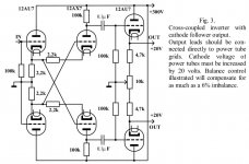
The uploaded improved Van Scoyoc phase splitter dates to the end of the 1950s and is mentioned in this thread.
IMO, further enhancement would CCS load the 'X7 gain sections and use ZVN0545A source followers DC, not cap., coupled to the 'X7 sections as the O/P buffers. Even driven single ended, a 2 VRMS I/P signal would be elevated to approx. 100 VRMS.
Broskie made a point that employing a negative rail allows the I/P cathode follower load resistors to increase, which results in greater overall linearity.
Would it be possible to use a CCS and a negative rail, instead of resistors, under the I/P cathode followers? If it works, such an arrangement would allow the non-inverting I/P to be used for NFB, as was done in "El Cheapo" (schematic uploaded).
Attachments
- Status
- This old topic is closed. If you want to reopen this topic, contact a moderator using the "Report Post" button.