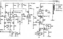
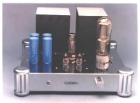
Most of the design for the bigger tubes i searched used the fixed biasing, eg. Ongaku 211, Ankoru 845, and many others. Is there any specific reasons why self-bias using high power resistors at the DHT cathode is not use, be it for sonic or safety reasons? can anyone enlighten?
It makes me dizzy just to think about itthe design u mentioned sounds interesting
To give a bit more input on fixed vs. cathode bias, as HollowState says, efficiency has a lot to do with it. Another is the class of operation and a third is consideration of B+.
At first glance, cathode bias appears to suit Class A perfectly well; however, it does have its downside. You need a higher B+ because some of it is taken up with the cathode bias voltage. Another disadvantage is the need for cathode bypass caps. These need to be of high capacitance and are usually electrolytic type, which do not give the best sound.
You can avoid using a bypass cap if you use Class A push-pull with a single shared bias resistor (or a CCS); however, the OP tubes must be really well-matched or else you will get a DC offset in the transformer primary, causing some DC saturation of the core. Separate cathode bias resistors give a useful degree of automatic balancing, but then you need bypass caps.
In any (PP) class other than A, fixed bias is called for. Sure, mild Class AB1 (close to Class A) can use cathode bias but separate, bypassed cathode resistors are essential and efficiency is impaired. With deeper Class AB1 and with Class AB2 or Class B, cathode bias is not viable. Fixed bias is the only solution.
Bias
Commstech:
About tube bias, there are 3 types:
1, fixed bias
2, self bias
3, provided bias
Fixed bias is derived from power source, a negative voltage rectifier and trimmed to a desired voltage and feed to the grid leak resistor.
self bias is a positive voltage appears at the cathode when plate current flows, a voltage dropped on the cathode resistor. this voltage with respect to grid, it just turns up side down and become a negative bias voltage. the number of voltage appears at cathode, the same voltage bias.
provided bias is used in transmitter driver or final stage, usually transmitter final stage works on class C, no external bias were supplied, the tube gets it's bias at the driver stage, the coupling resonance coil. at RF positive cycle, the tube flows at max current, and cuts off at negative cycle, then the negative cycle is the bias of the tube. C type amplifier can deliver the highest power than ever been. For details, refer to RF amplifier app. note.
One can shorted the plate to ground, ( with plate load ) and flow up the cathode with a negative voltage supplied, what happen??? The tube still at normal working condition. This is similar to self bias.


we switch around the voltage, then becomes bias
Commstech:
About tube bias, there are 3 types:
1, fixed bias
2, self bias
3, provided bias
Fixed bias is derived from power source, a negative voltage rectifier and trimmed to a desired voltage and feed to the grid leak resistor.
self bias is a positive voltage appears at the cathode when plate current flows, a voltage dropped on the cathode resistor. this voltage with respect to grid, it just turns up side down and become a negative bias voltage. the number of voltage appears at cathode, the same voltage bias.
provided bias is used in transmitter driver or final stage, usually transmitter final stage works on class C, no external bias were supplied, the tube gets it's bias at the driver stage, the coupling resonance coil. at RF positive cycle, the tube flows at max current, and cuts off at negative cycle, then the negative cycle is the bias of the tube. C type amplifier can deliver the highest power than ever been. For details, refer to RF amplifier app. note.
One can shorted the plate to ground, ( with plate load ) and flow up the cathode with a negative voltage supplied, what happen??? The tube still at normal working condition. This is similar to self bias.


we switch around the voltage, then becomes bias
commstech said:Most of the design for the bigger tubes i searched used the fixed biasing, eg. Ongaku 211, Ankoru 845, and many others. Is there any specific reasons why self-bias using high power resistors at the DHT cathode is not use, be it for sonic or safety reasons? can anyone enlighten?
Those "big tubes" mentioned there are low u triodes. That means a relatively high negative bias to set a Q-Point. Cathode bias would rob Vpk. The high wattage resistors tend to be more inductive, and really should not be used if fidelity is the design goal. Even if you parallel up a whole bunch of smaller resistors, you still have the heat problem. Besides, fixed bias tends to produce less distortion, sometimes much less.
Other times, the "big tubes" were originally designed as RF finals. In these cases, the amplification factors are so high that they require positive grid bias to set any sort of practical Q-Point. Here, cathode bias isn't possible anyway.
Re: Re: Self Bias and Fixed Bias for Big Tubes?

Ahhhh......this is the motherhood statement that helped me in the decision for what method of biasing...Miles Prower said:
.....really should not be used if fidelity is the design goal. .
...
fixed bias in IT coupled designs
What is better in an amp that is transformer coupled to the power tube. Fixed bias into the secondairy of the transformer and a grid resistor to ground. Or fixed bias into the grid resistor and the center tap of the transformer attached to ground ?
What is better in an amp that is transformer coupled to the power tube. Fixed bias into the secondairy of the transformer and a grid resistor to ground. Or fixed bias into the grid resistor and the center tap of the transformer attached to ground ?
not exactly. Cathode bias works fine with the 6L6 family. IF you want to get crazy with the plate voltage, then you have an incentive to use fixed bias. It also bears nothing that the screen grid (and thus the voltage applied to the screen) actually exerts more control over the tube than the plate. Normally, in pentode mode, 250 ohms is good on a 6L6 (or member of the 6L6 familyi) and you waste very little power in cathode-bias mode UNLESS you push the plates beyond 400 volts AND raise the screen voltage as well. Then the difference in power output between cathode and fixed bias will become relevant. Look at the tube data sheets, study them a bit. The whole story is right there. But, it really depends on the TUBE, and not necessarily how powerful the tube is. The 7591 is normally run in fixed bias for a reason and it's LESS powerful than the 6L6GC. Bottom line, in a 6L6 with plate voltage of 400 or maybe a bit more and a reasonably sane screen voltage (say, less than 350), you have no incentive to use fixed bias over cathode bias.Large tubes like these require higher voltages to operate correctly. In order to use self (cathode) bias, a large value resistor would be needed which would seriously hurt efficiency. So it's a matter of practicality. It also gived better control.
Victor
Yes exactly. We were not talking about 6L6s or 7591s. These are not "large tubes". The original poster was refering to 211s and 845s. These tubes work at 1000 plate volts (or more) and negative 80 and 150 grid volts respectively because of their low µ. Under these conditions fixed bias is far more pragmatic.
With smaller tubes like the 6L6 etc, I tend to agree with you. Self bias can be more easily implemented because the losses are smaller. Both bias systems have their pros and cons with these smaller tubes. However, I am of the opinion that fixed bias is generally superior for all but the lowest power output tubes. Self bias is popular with some DIY's because it is simpler, and it raises the bottom line for manufactures. So here, it comes down to designer's choice.
With smaller tubes like the 6L6 etc, I tend to agree with you. Self bias can be more easily implemented because the losses are smaller. Both bias systems have their pros and cons with these smaller tubes. However, I am of the opinion that fixed bias is generally superior for all but the lowest power output tubes. Self bias is popular with some DIY's because it is simpler, and it raises the bottom line for manufactures. So here, it comes down to designer's choice.
- Status
- This old topic is closed. If you want to reopen this topic, contact a moderator using the "Report Post" button.
- Home
- Amplifiers
- Tubes / Valves
- Self Bias and Fixed Bias for Big Tubes?

