Bembel,
I think that the 2 parts are connected in parallel for 120 mA. current capability.
A 4 diode bridge is a 4 diode bridge. The forward drop in Selenium is greater than the forward drop in Silicon.
Don't bother testing them. Selenium rectifiers are ticking toxic time bombs. Replace those parts with 4X UF4007s and a dropping resistor.
Thx Eli, thanks for your answer but Ithink that the HV is floating each side of ground through an 85A2,
I found the problem, a dead nuvistor (on two) a the entrance too bad because I have no spare ones !
Any way I wonder what formula use to calculate the dropping resistor for general Selenium bridge rectifier replacement.
I found the problem, a dead nuvistor (on two) a the entrance
too bad because I have no spare ones !Any way I wonder what formula use to calculate the dropping resistor for general Selenium bridge rectifier replacement.
I get a new 7587 nuvistor yesterday,
The diff amp can now be balanced, great.
But it seems that selenium rectifier has lost efficiency ! B+ is 355V after rect. in place of 420V, the electrolytics are OK or replaced yet.
Any tricks to compute the additional resistance when replacing with a Si bridge is welcome
Thanks.
The diff amp can now be balanced, great.
But it seems that selenium rectifier has lost efficiency ! B+ is 355V after rect. in place of 420V, the electrolytics are OK or replaced yet.
Any tricks to compute the additional resistance when replacing with a Si bridge is welcome
Thanks.
Hi Bembel,
I suspect based on your pix that those selenium half bridges can be replaced with a single conventional silicon rectifier bridge of > 800piv 1A - 2A rating to be conservative. I would install the rectifier first with a 100 ohm 2W series resistor in one of the ac legs and then measure how far off you are and increase or decrease the value until you are close.
Those rectifiers are toxic and should be regarded as hazardous waste and if your community has recycling provisions for scrapped electronics I would take them there.
Note that the old nuvistors might not be bad if the filament voltage is low due to a bad rectifier. (assuming dc heating)
Edits for clarity and to correct an error

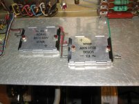
bembel said:Here is a pict of the bridge rectifier, each block has 3 legs external metal box contacts the chassis.
I would be super to have an equivalent schematic (what's the typical drop in such a bridge? any special way to test them ?)
Salut bembel!
I think that each one of the two rectangular boxes consists of 2 diodes connected in series - the + describing the cathode of one diode, the - the anode of the other. AC lead is the center tap between these 2 diodes.
If now two of these boxes are connected as shown, the two cathodes (+) and the two anodes (-) give the DC poles and the two AC leads the AC poles of an ordinary 4-diode bridge.
Must say this is quite an unusual assembly, since I know these forms of rectifiers as full bridges (the ordinary tube radio set bridge), but 500 V also is quite high for such devices - usual values were 250 V / 100 mA. The metal box is electrically isolated from the diodes and gives contact to a heatsink.
And - quite probably - it isn't selenium which has been used in these boxes as a semiconductor, but Cu2O - "copper oxydul" (at least it is called like this in Germany) - but equally as toxic as selenium.... Voltage drop is a bit less than in tube rectifiers, but still far much than in si-diodes.
Salut de Sarrebruck
Uli
IIRC Copper oxide was used mainly in low voltage rectifiers, given the brand and vintage I still think it likely that those are selenium.. Either way both are toxic and should be handled with care. (Don't disassemble them!) If they burn up the smoke from them is extremely toxic so I would replace as soon as possible.
edit: fix typo
edit: fix typo
Thx all, I've just came back home.
all I can tell for now, is that the sel. or Cu. assembly is a full wave bridge on the schematic.
I'll scan it tonight , just wait an hour or so....
Thanks again for your answers I'm really puzzled about that, and I'm really grateful with your outputs. (it serves me)
As bthe beast is a VTVM all inputs regarding stability are most welcome.
just wait a few mins. for the schematic.
thx again
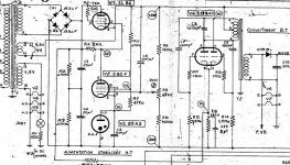
here it is ...
I have :
* ~350V after rectification. (instead of 420V)
* 230V instead of 200V as B+ (I was a bit confused, the whole thing is floating "circled" (-200) seems to be the minus side, not earth nor ground (otherwise specified like the 4V/ground for the nuvistors filaments @the most right V6-V7) other potentials circled are refering to this "minus side or cold point"
* more than 220V @ ECC82's anodes (more important this B+ sets the precise 4V nuvistor's (diff amp input) filaments supply)
I have yet measured the carbon comp resistors across the reg. supply and the drift is only between 10%, also voltage across 85A2 is good, caps are good also. And I've replaced CR2 for a BYV92, C10 & C22 are new.
Any idea prior to the selenium bridge (CR1-CR2) ?
Attachments
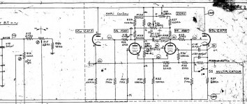
here's the entrance ...
I have strange voltages on nuvistors, have to measure again... (this is a pb. of reference "ground". Anyway, the schematic is really not clear to me about that)
In any case I've set V6-V7 filament supply to 4V (...leading yo 220V B+ ...)
PS: The missing part under the schematics are only attenuators & the tube (diode) AC probe. Aside this, what's mean "IIRC" Kevin ??? Sorry, i'm french ;-)
Attachments
Nuvistor Heater Volts....
http://www.drtube.com/tubedata.htm
Here, around halfway down is the data sheet for the 7587 Nuvistor....
It reckons that the Heater volts should be 6.3V AC or DC, and not 4V. this could be causing your weirdness around the Nuvistors voltage-wise, as at 4V they are well under-heated...
I would also replace those old 'plate-rectifiers', as when they fail, which they do,- The smell is really something Horrible, and lingers for weeks!--Almost like rotten fish, with something else horrible too...
I had an old radio that had a plate-rec like that which failed years ago...I can still remember the stench!
Hi Bembel,
"IIRC" Means "If I recall correctly" - old internet shorthand from the days when surfing meant Usenet and there was no web...
That reference to -200V is just a nomenclature for the negative side of the supply, it could equally be 0V or GND, etc...
Adjust R9 to set the voltage to exactly 200V between +200V and -200V lines. Check the value of R8 and R10, they must be close to the values cited, and should not be carbon for long term stability.
First replace those rectifiers! It will have to be set again probably once you do this.
Yes 4V is very wrong for the filaments in the 7587. There is another problem, but fix one at a time. Get the above stuff sorted out and you may find some of the other issues go away. (+230V and 350V issues.)
The E82CC is a high frequency inverter to produce filament voltage for the 7587 - this is rectified to dc. Make sure that the rectifier is good - replace with a schottky if not. (Don't use a regular diode) The 500uF cap can be replaced with a 470uF and probably should.
Edit: Clarification
Hi Bembel,
Replace C8 with a 10uF electrolytic, if this is bad the inverter will not operate correctly.
Selecting the 250V tap would result in the voltages being about 6% low, selecting the 220V tap would result in the voltages being about 7% high. I'd probably make the same choice you did for safety reasons - neither is optimum though.
Re: Nuvistor Heater Volts....
Thanks all,
The right good & only service manual (that I bought for 20€) specify that the most important point of calibration is the
4V filament supply for the nuvistors (as stated on the schematic)
I don't know what they had in mind but ... (and they even say prior to HV regulation as it's a coupled tuning)
Kevin, the caps you mentioned have been replaced (preventivly) as the diode did (BYV96), I'll check the feedback network. Also thx for your english lesson, it's not the 1st time I saw "IIRC" wondering the meaning... hmmmh... Could you tell me about IMO or IMHO don't remember ?
PS: everyone seems to agree with that burned selenium smell!
Alastair E said:http://www.drtube.com/tubedata.htm
Here, around halfway down is the data sheet for the 7587 Nuvistor....
It reckons that the Heater volts should be 6.3V AC or DC, and not 4V. this could be causing your weirdness around the Nuvistors voltage-wise, as at 4V they are well under-heated...
I would also replace those old 'plate-rectifiers', as when they fail, which they do,- The smell is really something Horrible, and lingers for weeks!--Almost like rotten fish, with something else horrible too...
I had an old radio that had a plate-rec like that which failed years ago...I can still remember the stench!
kevinkr said:Hi Bembel,
"IIRC" Means "If I recall correctly" - old internet shorthand from the days when surfing meant Usenet and there was no web...
That reference to -200V is just a nomenclature for the negative side of the supply, it could equally be 0V or GND, etc...
Adjust R9 to set the voltage to exactly 200V between +200V and -200V lines. Check the value of R8 and R10, they must be close to the values cited, and should not be carbon for long term stability.
First replace those rectifiers! It will have to be set again probably once you do this.
Yes 4V is very wrong for the filaments in the 7587. There is another problem, but fix one at a time. Get the above stuff sorted out and you may find some of the other issues go away. (+230V and 350V issues.)
The E82CC is a high frequency inverter to produce filament voltage for the 7587 - this is rectified to dc. Make sure that the rectifier is good - replace with a schottky if not. (Don't use a regular diode) The 500uF cap can be replaced with a 470uF and probably should.
Edit: Clarification
Thanks all,
The right good & only service manual (that I bought for 20€) specify that the most important point of calibration is the
4V filament supply for the nuvistors (as stated on the schematic)
I don't know what they had in mind but ... (and they even say prior to HV regulation as it's a coupled tuning)
Kevin, the caps you mentioned have been replaced (preventivly) as the diode did (BYV96), I'll check the feedback network. Also thx for your english lesson, it's not the 1st time I saw "IIRC" wondering the meaning... hmmmh... Could you tell me about IMO or IMHO don't remember ?
PS: everyone seems to agree with that burned selenium smell!
Hi Bembel,
Here's some useful jargon, and this reply is OT (off topic)
"IMO" In my opinion
"IMHO" In my honest opinion
"AFAIK" As far as I know
"BTW" By the way
"YMMV" Your mileage may vary (should that be kilometers per liter?)
"OTOH" On the other hand
"JMTCW" Just my two cents worth
"LOL" Laugh out loud
"ROFLMAO" Roll on floor laughing my a** off
Truthfully we should probably refrain from using these contractions as I am sure it causes lots of non native English speakers some problems.
a bien tot
Happy new year to all.
I was on vacation, last two weeks...
And am back now.
I am going to replace the selenium full wave bridge today.
I will try with a 100 ohms on one AC leg before the bridge as Kevin adviced. But when the value will be settled, what's the more "elegant way"? 2 resistors before the bridge or one after ??? Any other suggested value than 100 ohm as the starting point now that we have the schematic ???
thanks again
Best wishes for 2007.
PS:The "strange" 4V to ground specification for the nuvistors filaments, is stated after CR3 so real filament "AC" voltage should be a bit higher .
some measures...
some measures before selenium replacement:
AC voltage before bridge is 337VAC
Rectified voltage starts @415VDC "cold" falling quickly to 357VDC when filaments are heated and load is coming . Schematic is stating a 420VDC under load after bridge.
maybe the sel rect isn't up to spec anymore (no smell at all) ?
Anyway 337x1.41= a theorical 475VDC so it cause a:
60VDC voltage drop @ no load (the 415V of the begining seems OK)
120VDC voltage drop under load. (seems far to much)
The fuse being 0.63A SB from 115V to 250V mains, I think the B+ is at least less than 150mA.
Any suggestion ?
- Status
- This old topic is closed. If you want to reopen this topic, contact a moderator using the "Report Post" button.
- Home
- Amplifiers
- Tubes / Valves
- Can anyone help, identifing selenium bridge hookup please.