Hey Folks,
Flipping through old issues of Glass Audio, I came across Rickard Berglund's perfect regulator (4/96 p. 65):
Any possibility of substituting a low voltage regulator tube like the 0A3 (75V) for the zener? What component values would be altered? I'm afraid I have less knowledge than enthusiasm. Any suggestions would be appreciated.
Flipping through old issues of Glass Audio, I came across Rickard Berglund's perfect regulator (4/96 p. 65):
An externally hosted image should be here but it was not working when we last tested it.
Any possibility of substituting a low voltage regulator tube like the 0A3 (75V) for the zener? What component values would be altered? I'm afraid I have less knowledge than enthusiasm. Any suggestions would be appreciated.
CarlyBoy said:Hey Folks,
Flipping through old issues of Glass Audio, I came across Rickard Berglund's perfect regulator (4/96 p. 65):
Any possibility of substituting a low voltage regulator tube like the 0A3 (75V) for the zener? What component values would be altered? I'm afraid I have less knowledge than enthusiasm. Any suggestions would be appreciated.
leave it as is;
with gass toob instead of zener -you'll burn at least 10-15mA of adittionall current.
anyway-gass toob can be used as reference in better stab or even in stab constructed for known circuit,not universal one-like this .
this perfect reg can be much better ,with adition of output cap,small cap from output to wiper of lower pot......and even another zenner-included in output voltage divider upper "half".
in this way (with another zenner) ECC LTP is from both sides leaned on solid (in this case bridge) reference.........
bla bla -it's pretty late here .............zzzzzzzzzzzzzzzz
Re: Re: Perfect tube regulator
Hi Choky,
Yes, 100-220nF or something, so that the rest of the ripple is coulped for counter-action to the diff amp. Also, a very high ohm resistor from EL86 plate to diff amp input would implement forward regulation (further improving regulation of changing mains voltage).
Accordingly, here is a much better implemented (and performing) EL86 based regulated PSU on my homepage.
Tom
Hi Choky,
this perfect reg can be much better ,with adition of output cap,small cap from output to wiper of lower pot......
Yes, 100-220nF or something, so that the rest of the ripple is coulped for counter-action to the diff amp. Also, a very high ohm resistor from EL86 plate to diff amp input would implement forward regulation (further improving regulation of changing mains voltage).
Accordingly, here is a much better implemented (and performing) EL86 based regulated PSU on my homepage.
Tom
I'd watch out about modifying this design, if you read the article very carefully you will find that there are some interesting twists to this design in terms of the way feedback is applied. (Like the design has positive feedback implicit in its operation.) Don't bypass the pots with caps! Set up as described in article is not intuitive, follow to the letter to get it to work properly.
You could I think substitute a 5651 for the zener which would result in better drift and voltage stability than the typical zener offers. Do this only after you get the actual circuit to work.
I use pentode connected EL84/6CA7/6L6/6550 with 12AX7 cascode error amplifier (tube is not the optimum choice for a cascode, but the ~ 46dB loop gain is enough for my purposes, cheap, and stands off lots of voltage ok) and 5651 reference. I can furnish details at some point if there is interest. Note in lower voltage versions you can probably use the EF86 in place of the cascode to good effect, but I have not tried this yet. Ripple rejection >60dB typ, low drift, good line and load regulation <1% typ and low output z. It's simple too, reliable - variants of this circuit are in almost everything I ever built for sale.
kevinkr said:I can furnish details at some point if there is interest.
Fer shure!
")
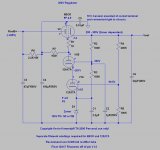
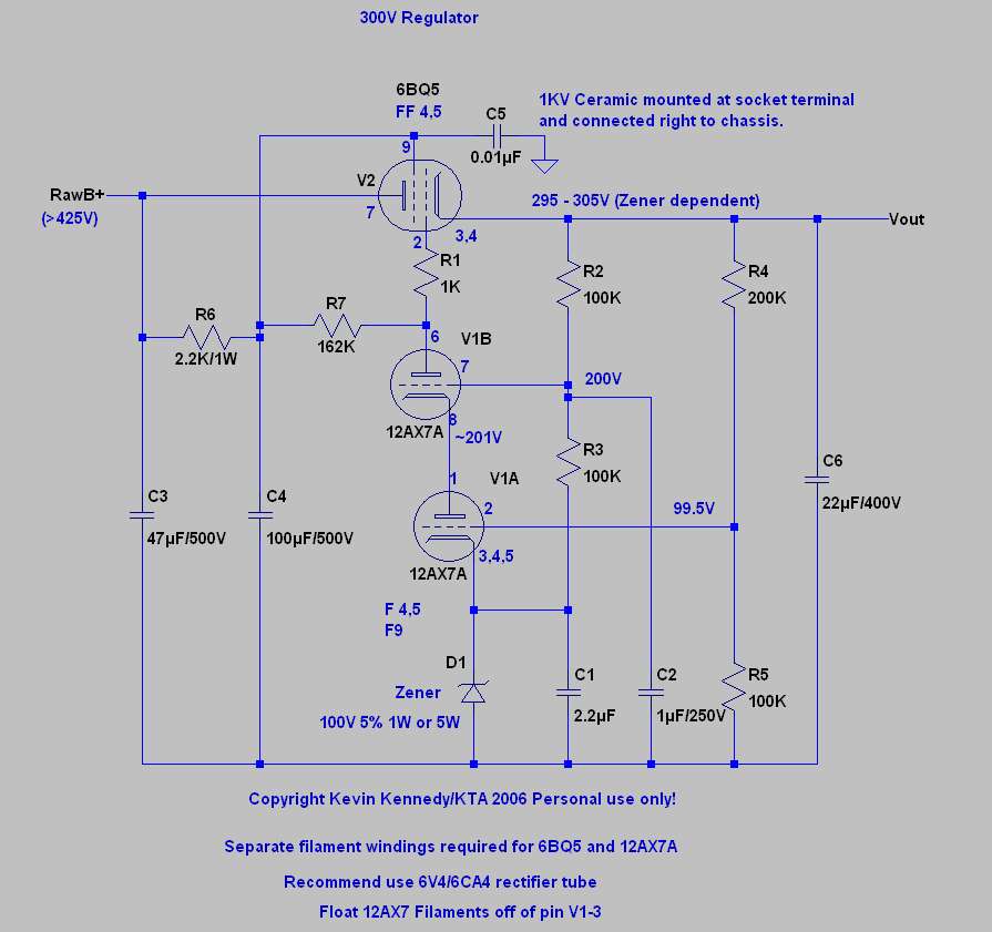
Here is my standard 300V regulator, note that it is zener based. Getting good performance with the 5651 gas reference is a little trickier. This design works right out of the box. Note I provide it for none commercial use only.
The voltage can be easily reset for different output values from about 200V to 350V with a few component value changes which I will happily provide to anyone who asks.
To make life easier for the 6BQ5 I recommend a tube rectifier, that said it works fine with ss rectification to output voltages of 300V, higher than that a tube rectifier is de riguer to prevent pass tube arcing. Currents higher than 40mA should use the 6L6 otherwise its the same.
Keeping the noise down on the output depends on how clean the screen supply is, and how much feedback margin is available. Typically I aim for a margin of >30dB if possible.
Open loop gain is in the range of 43dB +/-3dB and I recommend not scaling voltages by more than a factor of 3 to 4 in order to maintain sufficient loop gain for good regulation.
The cascode error amplifier works best with output voltages of 200V and above, the only limitation is to avoid exceeding the voltage ratings of the 12AX7A - in practice up to 500V output voltage is practical with a 6550 pass tube and a few other minor changes.
Note that you must provide separate filament supplies for the 6BQ5 and 12AX7A. Regulated dc on the 12AX7A filament is not necessary but does not hurt either. A 6CA4 may be operated on the same winding as the 6BQ5 if necessary.
Warm up drift is mostly dependent on the zener chosen, and I recommend 5W types for lower drift. Once stable the voltage should drift less than 1% in a 24 hr period.
Output ripple of <1mVrms is possible with careful layout and a 12AX7LPS in the error amplifier. Line and load regulation is better than 1% no load to full load as long as the raw supply is at least 100V greater than the output voltage at lowest line voltage encountered.
Attachments
Hi Sy,
Yes I just connect the cathode of the pass tube directly to the filament (in this case pins 3 &4) - this obviously necessitates the use of a separate filament winding for the pass tube and error amplifier.
I noticed I forgot to show the ground connection on the negative side of the supply. The center tap of the power transformer (or negative lead of bridge rectifier if used) should be connected right at the very first filter cap. I usually bring a bus ground back to this point which is usually also the point at which I make a single connection to chassis. This is also usually the point I recommend connecting the ground return from the load. (Modified star ground basically)
Incidentally with really great care in layout it is possible to get ripple and noise down below 100uVrms at the output.
I know the 12AX7 is not nearly the optimum choice in terms of transconductance for a cascode amplifier configuration, but despite this the performance is actually quite good, and the 12AX7 can stand off quite high voltages with a little aforethought. I umm have done 1KV regulators with only a few changes to the topology.. 

Yes I just connect the cathode of the pass tube directly to the filament (in this case pins 3 &4) - this obviously necessitates the use of a separate filament winding for the pass tube and error amplifier.
I noticed I forgot to show the ground connection on the negative side of the supply. The center tap of the power transformer (or negative lead of bridge rectifier if used) should be connected right at the very first filter cap. I usually bring a bus ground back to this point which is usually also the point at which I make a single connection to chassis. This is also usually the point I recommend connecting the ground return from the load. (Modified star ground basically)
Incidentally with really great care in layout it is possible to get ripple and noise down below 100uVrms at the output.
I know the 12AX7 is not nearly the optimum choice in terms of transconductance for a cascode amplifier configuration, but despite this the performance is actually quite good, and the 12AX7 can stand off quite high voltages with a little aforethought. I umm have done 1KV regulators with only a few changes to the topology..
Here's a simple series pass regulator. Not designed for tremendous output current, but still the 6AQ5 runs far below its Pd max rating. This one uses the 6CB6A high gain pentode for the error amp. Works pretty good in that it'll hold the output voltage to within 0.8V for a 40V rail variation. The nice thing about that 6CB6A is an unusually high Vhk rating of 200V. Most small signal VTs have a rating more like 90V.
As for residual AC, this regulator is dead quiet. While o'scoping the output, whatever ripple was there was buried in the noise coming from a 50KW clear channel AM xmtr about 30 miles away.
This could easily form the basis for a beefier series pass regulator.
[img=http://img216.imageshack.us/img216/1601/screenregyj8.th.gif]
Hp400d
Hi,
I really like the design of the HV regulator which is used in the HP400D audio volt meter. It provides very clean and fast response for any changing loads. The driver tube is 6U8A. I used paralleled 6BX7 instead of the 12B4 regulator for higher current. I also employed a C-L-C filter before the regulator tube. Really cool circuit.
Johnny
Attachments
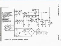
Yes, studying designs from the major test equipment manufacturers is a good way to pick up circuit ideas. Arguably, the pinnacle of vacuum tube analog circuit engineering can be seen in HP and Tektronix designs from these years. Here's another example of tube regulation from the Tektronix 531/541 scope:
Attachments
Here is my standard 300V regulator, note that it is zener based. Getting good performance with the 5651 gas reference is a little trickier. This design works right out of the box. Note I provide it for none commercial use only.
The voltage can be easily reset for different output values from about 200V to 350V with a few component value changes which I will happily provide to anyone who asks.
To make life easier for the 6BQ5 I recommend a tube rectifier, that said it works fine with ss rectification to output voltages of 300V, higher than that a tube rectifier is de riguer to prevent pass tube arcing. Currents higher than 40mA should use the 6L6 otherwise its the same.
Keeping the noise down on the output depends on how clean the screen supply is, and how much feedback margin is available. Typically I aim for a margin of >30dB if possible.
Open loop gain is in the range of 43dB +/-3dB and I recommend not scaling voltages by more than a factor of 3 to 4 in order to maintain sufficient loop gain for good regulation.
The cascode error amplifier works best with output voltages of 200V and above, the only limitation is to avoid exceeding the voltage ratings of the 12AX7A - in practice up to 500V output voltage is practical with a 6550 pass tube and a few other minor changes.
Note that you must provide separate filament supplies for the 6BQ5 and 12AX7A. Regulated dc on the 12AX7A filament is not necessary but does not hurt either. A 6CA4 may be operated on the same winding as the 6BQ5 if necessary.
Warm up drift is mostly dependent on the zener chosen, and I recommend 5W types for lower drift. Once stable the voltage should drift less than 1% in a 24 hr period.
Output ripple of <1mVrms is possible with careful layout and a 12AX7LPS in the error amplifier. Line and load regulation is better than 1% no load to full load as long as the raw supply is at least 100V greater than the output voltage at lowest line voltage encountered.
Hi Kevin,
I know is an old thread, could you tell me the component value changes for 280V?
TIA
Felipe
Hi Kevin,
I know is an old thread, could you tell me the component value changes for 280V?
TIA
Felipe
Add a 10 or 20k good guality pot (or trimmer) between R4 and R5 and adjust for desired voltage around 300V. Don´t use a dirty or old pot where the wiper can become disconnected from the track.
Thanks, guys, but no. Easiest just to change R4 to 180K.
Note that you can also shunt across R4 with a very good quality film cap, if you do this I would make R4 361K and R5 200K, and use a 0.22uF cap. This should reduce ripple at the output by about 10dB and reduce output impedance substantially at audio frequencies (not DC).
I would recommend further changes, I no longer connect the filament to cathode directly even with the dedicated winding due to common mode ripple injection into the output DC. I now recommend using a 470K resistor from cathode to filament and a 0.22uF 400V film cap from that point to ground.
FWIW I also no longer recommend this circuit be used below 250V, nine years is a long time. (And in that case a lower voltage zener must be used)
See my Muscovite thread over in analogue source:
http://www.diyaudio.com/forums/analogue-source/213769-muscovite-6s3p-tube-phonostage.html
FWIW I have always thought the thread title was a bit unfortunate, obviously my regulators aren't perfect or I would not keep attempting to improve them.. lol I prefer tube regulators in HV applications to solid state for a variety of reasons from reliability to personal preference, but the typical monolithic HV regulator will unquestionably have better measured performance than most tube based designs. Mine are very simple with a measured set of trade offs between cost, complexity and performance. They do however work well at least in my opinion.. lol
- Status
- This old topic is closed. If you want to reopen this topic, contact a moderator using the "Report Post" button.
- Home
- Amplifiers
- Tubes / Valves
- Perfect tube regulator