"You're talking shelf speakies or what?
Nah,man...A speaker,a floorstander I mean,should have a solid reference to ground."
Both - Boston A-40 6 1/2 " 2 way, and Canton 12" 3 way.
Similar result both types - nicer overall, higher SPL.
"Cones with gradual damping do exist and are a good alternative."
Any examples ?.
Ta, Eric.
Nah,man...A speaker,a floorstander I mean,should have a solid reference to ground."
Both - Boston A-40 6 1/2 " 2 way, and Canton 12" 3 way.
Similar result both types - nicer overall, higher SPL.
"Cones with gradual damping do exist and are a good alternative."
Any examples ?.
Ta, Eric.
SAMPLE
Hi,
Here's just one I came across while surfing:
CLEARLIGHT
There must be other models out there though.
When put on springs?
I find that odd,one would expect a less tight bass and less well defined stereo image.
Could be the type of floor plays a role,still...odd.
Cheers,")
Hi,
Any examples ?.
Here's just one I came across while surfing:
CLEARLIGHT
There must be other models out there though.
Similar result both types - nicer overall, higher SPL.
When put on springs?
I find that odd,one would expect a less tight bass and less well defined stereo image.
Could be the type of floor plays a role,still...odd.
Cheers,
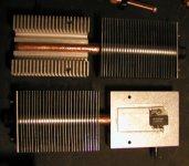
analog_sa said:Peter
Your latest clone is giving me the creeps. Apart from a nice but wasted chunk of acrylic what are these horror structures on the side? I hope selenium rectifiers, as if they're heatsinks all the vibtration controll efforts are wasted. They do remind of late seventies Sony and ring in most unmusical manner.
cheers
peter
Maybe it's wasted, maybe not. I was a bit afraid too, but the fins have very low mass and from my initial test they vibrate much less than conventional fins or chassiss panels. The big chunk of acrylic, together with the other piece supposed to act as a sink and absorb any vibrational energy and through the spike release it to the supporting platform. If ringing is a problem, I can always reduce it with a bead of silicone between the blades. But the look of the heatsinks was so appealing that I couldn't resist the temptation to implement them this way. In a large extend this is an experiment and only the listening tests will show if I was right.
Attachments
I'm sorry but I feel you people are totaly missing the point here.
The only way to achieve true total harmonic sound is to splay the chassis properly. Only by achieving the proper free air resonance of the chassis are you able to achieve the true harmonic capabilities of the chassis. The chassis must be suspended exactly 3.7feet above the floor using monofilament fishing line of at least 7lbs test. The chassis must be kept a minimum of 2.2 ft from the nearest wall or object. The downward angle must be set between 15 and 17 degrees for the electrons to flow properly if the chassis is facing north or south, 18-22degrees if it faces east or west.
The only way to achieve true total harmonic sound is to splay the chassis properly. Only by achieving the proper free air resonance of the chassis are you able to achieve the true harmonic capabilities of the chassis. The chassis must be suspended exactly 3.7feet above the floor using monofilament fishing line of at least 7lbs test. The chassis must be kept a minimum of 2.2 ft from the nearest wall or object. The downward angle must be set between 15 and 17 degrees for the electrons to flow properly if the chassis is facing north or south, 18-22degrees if it faces east or west.
Yes, but you are forgetting the pull of the moon. You should only play the amp during the time the moon is on the other side of the earth or at its peak above you, whichever sounds better. This, of course, will only give you a couple hours twice a day to listen it. There are several good tidal watches out there that help you time this. 
So I have to point my naked butt towards it? I don't know if that would produce an attractive image, though it would certainly be more tangible after a good curry.Philo said:Yes, but you are forgetting the pull of the moon. You should only play the amp during the time the moon is on the other side of the earth or at its peak above you, whichever sounds better. This, of course, will only give you a couple hours twice a day to listen it. There are several good tidal watches out there that help you time this.
I hope none of the neighbours see me. They think I'm strange enough as it is.
SPAGETTI
Hi,
LOL.
I read that story too.
Can't remember where though...
As if Italy has silver mines?
No way,Jose!
Cheers,
Hi,
LOL.
I read that story too.
Can't remember where though...
This reminds me of 10,000$ pair of cables or audio note useing only Italian silver
As if Italy has silver mines?
No way,Jose!
Cheers,
Re: SILVER SPAGETTI
I am only reading the AD's. I use surplus copper wire myself.
See link
http://www.audionote.co.uk/cabs.htm
Regards
Robert Morin
Hi fdgrovefdegrove said:Hi,
LOL.
I read that story too.
Can't remember where though...
As if Italy has silver mines?
No way,Jose!
Cheers,
I am only reading the AD's. I use surplus copper wire myself.
See link
http://www.audionote.co.uk/cabs.htm
Regards
Robert Morin
COLD DRAWN SILVER SPAGETTI
Hi,
Here's another good laugh from that ad:
Just figure a small Italian pulling the silver ingots through the die...
No,no I can tell the world where the AN silver comes from...should I?
Cheers,
Hi,
Here's another good laugh from that ad:
we are now able to offer these fine cold drawn A**** N***™ silver wires
Just figure a small Italian pulling the silver ingots through the die...
No,no I can tell the world where the AN silver comes from...should I?
Cheers,
Re: COLD DRAWN SILVER SPAGETTI
Do tell. I wonder if they polarize their wire like Hovland does?
Regards
Robert Morin
Ex. Hovland Tech.
ROTFALMAOfdegrove said:Hi,
No,no I can tell the world where the AN silver comes from...should I?
Cheers,
Do tell. I wonder if they polarize their wire like Hovland does?
Regards
Robert Morin
Ex. Hovland Tech.
Ex. Hovland Tech.?
Hi,
Since you ask.
Most of the specialty wires are sourced from the Phelps-Dodge (formerly Hudson Wire International) mining company in New Jersey.
The mines are in BC for silver+gold and in Chile (Atacama desert for copper).
If you need finished/insulated wire just ask their European director Mr.Karel De Laet.
DESKADEL
The audio cables are finished by BICC Vero in the U.K. for his company and were designed by yours truly.
Other than us being the best of friends I don't have any commercial relationship with this company.
AN buys raw silverwire through the same company.
You worked for Hovland Robert?
Maybe you could enlighten us on coupling caps.
Cheers,
Hi,
Do tell.
Since you ask.
Most of the specialty wires are sourced from the Phelps-Dodge (formerly Hudson Wire International) mining company in New Jersey.
The mines are in BC for silver+gold and in Chile (Atacama desert for copper).
If you need finished/insulated wire just ask their European director Mr.Karel De Laet.
DESKADEL
The audio cables are finished by BICC Vero in the U.K. for his company and were designed by yours truly.
Other than us being the best of friends I don't have any commercial relationship with this company.
AN buys raw silverwire through the same company.
You worked for Hovland Robert?
Maybe you could enlighten us on coupling caps.
Cheers,
Could anyone provide a reasonable explanation for the need to replace binding post nuts with non-conductive nuts? Why just the binding post and not all nuts? Was there a thread (pun intended) on this that I missed?
If this is true, why isn't cardas supplying them that way?
I would like to know if anyone has also tried this and has heard a difference. Peter, if you try this could you let us know if you hear a difference?
Thanx,
Joe
If this is true, why isn't cardas supplying them that way?
I would like to know if anyone has also tried this and has heard a difference. Peter, if you try this could you let us know if you hear a difference?
Thanx,
Joe
Re: Ex. Hovland Tech.?
Hi fdegrove,
I only worked at Hovland for 6 weeks. The caps are a turnkey operation for them. I was never privy to inner secrets. They even had me fixing their pre-amp with no schematics. On one hand they suffer from HUGE amounts of Audiophilla. On the other hand, the Amps/Preamps are hand built with gargantuan amounts of attention paid to quality details.
The sales guy there did not like it when I said that I had built better sounding amps and preamps on planks of wood with 1$ tv tubes. ---LOL---
Regards
Robert Morin
fdegrove said:
You worked for Hovland Robert?
Maybe you could enlighten us on coupling caps.
Cheers,
Hi fdegrove,
I only worked at Hovland for 6 weeks. The caps are a turnkey operation for them. I was never privy to inner secrets. They even had me fixing their pre-amp with no schematics. On one hand they suffer from HUGE amounts of Audiophilla. On the other hand, the Amps/Preamps are hand built with gargantuan amounts of attention paid to quality details.
The sales guy there did not like it when I said that I had built better sounding amps and preamps on planks of wood with 1$ tv tubes. ---LOL---
Regards
Robert Morin
GOING NUTS.
Hi,
All nuts would be better still.
The idea behind it is to use as little metal as possible.
I assume that is what J.Carr was pointing at.
Cheers,
Hi,
Why just the binding post and not all nuts?
All nuts would be better still.
The idea behind it is to use as little metal as possible.
I assume that is what J.Carr was pointing at.
Cheers,
Re: Re: Ex. Hovland Tech.?
Is that why you were only there for 6 weeks?
You may have built better sounding amps <i>in your mind</i>, but were any of them Stereophile Class A rated?
LMAO!Robert Morin said:The sales guy there did not like it when I said that I had built better sounding amps and preamps on planks of wood with 1$ tv tubes. ---LOL---
Regards
Robert Morin
Is that why you were only there for 6 weeks?
You may have built better sounding amps <i>in your mind</i>, but were any of them Stereophile Class A rated?
Joe:
>Could anyone provide a reasonable explanation for the need to replace binding post nuts with non-conductive nuts?<
I'm going to hold off on providing my own explanation, but I will mention that I started doing this after working on various types of grounding and power bus networks in circuit board layouts. I noticed that changes in where and how various components were tied into the ground and power bus networks affected both the measurements and the sound.
Maybe you can work out your own theories from this...
>If this is true, why isn't Cardas supplying them that way?<
Maybe this is true, but maybe I am just pulling your leg.
As far as I know, neither George nor Mary Cardas designs circuit boards as part of their jobs. And as I indicated above, _I_ likely wouldn't be doing this if I hadn't the experience of laying out circuits that are measureably and audibly sensitive to how they are grounded and powered.
>I would like to know if anyone has also tried this and has heard a difference.<
From his comments, I would guess that Frank has. Although I agree with him that part of the idea is to use as little metal as required, I find that the question is not only how much metal is used, but also where that metal is placed. If you take a certain volume of metal and locate it all on one side of the spade lug, this will not sound the same as if you had taken that same volume of metal and placed it on both sides of the spade lug.
But honestly, you don't have to go so far to get some idea of whether this is audible or not. The basic experiment is super-easy to do. No reason to not try it for yourself.
Well, OK. In case you think this is all too much effort, I'll make it even easier for you. If you have a pair of speaker cables that use banana plugs rather than spade lugs, hook up the speaker cables, and listen first with the end-nuts in place, and next without (because the cables use bananas, they will stay in place, with or without the end-nuts).
>Peter, if you try this could you let us know if you hear a difference?<
Assuming a single-ended output (not BTL), it may also be interesting to try changing just one end-nut out for a non-conductive replacement, then putting the conductive nut back and repeating the process on the opposite polarity, to see if there is a difference in effectiveness according to the polarity.
regards, jonathan carr
jcarr - Homepage - Enjoy some nice Pictures!
Enjoy some nice Amplifier!
Connoisseur Definitions(tm)
Connoisseur 3.0
Main amplifier board.
"Here you can see that by building our circuits 3-dimensionally in the air rather than relying only on a 2-dimensional circuit board, the circuit is much more compact than otherwise possible."
The 40-position coaxial volume control. Leadless non-inductive metal-foil resistors are soldered directly to the silver contacts.
/halo
Enjoy some nice Amplifier!
Connoisseur Definitions(tm)
An externally hosted image should be here but it was not working when we last tested it.
Connoisseur 3.0
An externally hosted image should be here but it was not working when we last tested it.
Main amplifier board.
"Here you can see that by building our circuits 3-dimensionally in the air rather than relying only on a 2-dimensional circuit board, the circuit is much more compact than otherwise possible."
An externally hosted image should be here but it was not working when we last tested it.
The 40-position coaxial volume control. Leadless non-inductive metal-foil resistors are soldered directly to the silver contacts.
/halo
- Status
- This old topic is closed. If you want to reopen this topic, contact a moderator using the "Report Post" button.
- Home
- Amplifiers
- Tubes / Valves
- The sound of chassis?