OK, after getting my PSU (more-or-less) designed, I want to add a time-delay relay so that a single switch can be used to turn on the 6.3VAC heater transformer before the B+ transformer gets switched-on.
My thoughts were that a time delay relay, while more expensive would be less stressful to implement. I would use the relay on the AC side of the B+ transformer, and it would be triggered when I switch on the heater transformer. Both switch and relay would be at the AC side of things.
Mouser stock a Magnecraft relay that'll tolerate 120VAC at 12A with a DPDT form that will allow for delays between 0.1 second and 10 hours. Of course, a 10 hour delay would be rather excessive and could result in considerable boredom, although there would be very little listening fatigue
At $36 it is not cheap, but is it likely to work? Does anyone have experience doing this?
Thanks,
Charlie
I use two timers in my amp (currently under production).
Both timers are initiated by the presence of voltage, i.e. when the main power switch is turned on. I take control power off the DC bus, which I use for running my filaments. The same approach, however, could be used if you are using AC filaments.
The first relay is set for one minute, and is installed in the return lead (center tap of transformer). Normally, it is off, so there is no B+. When this relay turns on, the B+ charges through a 10 ohm resistor, for limitation of inrush. I tried 100 ohm up to 1000 ohm, but the difference was somewhat trivial, in that either method either charges quickly or will not fully charge. It was not my intent to provide a slow start up, only control inrush.
Second timer is about 5 seconds, and shorts out the 10 ohm resistor. All these components are in the single return lead to the center tap of the transformer. I took this approach so I could guarantee all tubes are sufficiently heated before applying B+, and it also enables me to use my relay contacts in an AC circuit, as opposed to the common method of right in front of the first cap stage. Relay contacts prefer AC over DC, as the zero crossing aids interruption.
Sure, I could use a NTC or something, but I liked the idea of greater control, and ultimately having no resistive element in the B+ supply during normal operation. It also lets me use very small printed circuit board relays, instead of the larger ice cube style socket relays. It is therefore a little less expensive, and smaller. Small is good, as my amp is bursting at its britches.
I can provide a schematic if you are interested. It has a number of parts, but is compact.
That is certainly one way to approach it, however if one is using the auxiliary windings on the power tranny, you will also not be using those for the initial time delay. The idea was to have all other supplies up (filaments, bias) before the B+ initializes.
With regards to voltage rating of contacts, you need to consult the data sheet. My particular relays were Tyco/Schrack RT2 printed circuit mount. Each contact is rated up to 400VAC, with a dielectric strength of 1000VAC. The 400VAC rating is limited most by interrupting ability, not making ability. If you analyze the operation of the relay, it never interrupts load current. The relay contact opens after there is complete loss of AC power (at least in my design).
So, not only is the voltage rating of little concern, but I place the two contacts in series. Now I do not get exactly twice the voltage rating doing this, but contacts in series is a very common method of increasing contact life in higher voltage circuits. GE has been doing it for years in their power breakers' auxilaries, which need to handle 250VDC at 15A interrupting. Again, this is under the assumption that the contacts need to interrupt load current at rated voltage, something we don't need.
Finally, at the end of the day, the contacts are rated to interrupt 2000VA (that's a lot) and carry 10A continuously, while we require 100-300mA. That's very light duty for a relay. Putting the relay in the 120 side, however, will increase the current requirements.
At the end of the day, I think the most elegant solution is still the tube rectifier, but my preference is not to use them. I think the advantages of SS outweigh the burden of time delay circuits. Or, you could avoid delays altogether, as many believe cathode stripping is a non-issue at levels under 1000V.
BurnedFingers,
I will be building a diode-bridge PSU, so the heaters will not get chance to warm before full DC is applied.
It could be that cathode stripping is not going to be a problem, especially as I am going to be using very cheap tubes to begin with. Maybe once I decide to buy better quality tubes, I'll want to nurse them by installing some kind of delay relay.
Regards,
Charlie
I have used these timers with a relay. Simple and not real expensive. These are not normally available to the public. I am in a business where I can get them through a wholesaler. I am in no way connected with this auction.
http://cgi.ebay.com/ICM102-TIME-DEL...2001605QQihZ002QQcategoryZ78208QQcmdZViewItem
http://cgi.ebay.com/ICM102-TIME-DEL...2001605QQihZ002QQcategoryZ78208QQcmdZViewItem
Delay relays
When using two power transformers (one for B+, the other for the heaters), I've found the Amperite 115N060 delay relay tube to work nicely. It comes in a handy octal pinout - looks a bit like a 6SN7 but with more interesting internal structures. You can buy them for ~$15 and they come in 30, 60, 90, and 120 second delays.
When using two power transformers (one for B+, the other for the heaters), I've found the Amperite 115N060 delay relay tube to work nicely. It comes in a handy octal pinout - looks a bit like a 6SN7 but with more interesting internal structures. You can buy them for ~$15 and they come in 30, 60, 90, and 120 second delays.
No one mentioned using a ss pair or bridge diodes, even a ss doubler (whatever you need) which comes on rather instantly and then running that to the anode of a slow warm up TV damper tube. Pull the delayed B+ off it`s cathode. One tube solution. Parallel dampers if you need more current.
If you run a separate damper to separate filter banks from the main supply you will get some supply isolation which would be like separate power supplies for each channel. Run some commion prefiltering in front of the dampers.
If you run a separate damper to separate filter banks from the main supply you will get some supply isolation which would be like separate power supplies for each channel. Run some commion prefiltering in front of the dampers.
http://www.diyaudio.com/forums/showthread.php?s=&threadid=85002&highlight=
check out the schematic in that thread
enjoy
check out the schematic in that thread
enjoy
Bob is right, dampers do a good job in that position. I currently use an SS bridge rectifier and two 6D22S dampers in parallel as a delay. I know I'd do better with a hybrid SS / 6D22S bridge but I'd lose a bit more voltage than I can afford if I did that. As it is, I lose only 8v across the dampers @ 350mA. Delay is almost 30 seconds and turn-on is slow.
cbutterworth,
How about a custom made with a simple transistor a R/C and a relay
The power supply is taken from the heater circuit....
and the relay is used to switch-on the secondary of the B+
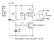
Take a look at the picture, sorry I didn't have the right values....
PS: I've done this in my SE 6C33C-B and works perfectly
for delaying the B+ Driver stage of 20 seconds and the
B+ of the final of 120 seconds...
Regards.
Alain.
How about a custom made with a simple transistor a R/C and a relay
The power supply is taken from the heater circuit....
and the relay is used to switch-on the secondary of the B+
Take a look at the picture, sorry I didn't have the right values....
PS: I've done this in my SE 6C33C-B and works perfectly
for delaying the B+ Driver stage of 20 seconds and the
B+ of the final of 120 seconds...
Regards.
Alain.
Attachments
Hi there, Could you put up the schematic you use for this approach.
I use two timers in my amp (currently under production).
Both timers are initiated by the presence of voltage, i.e. when the main power switch is turned on. I take control power off the DC bus, which I use for running my filaments. The same approach, however, could be used if you are using AC filaments.
The first relay is set for one minute, and is installed in the return lead (center tap of transformer). Normally, it is off, so there is no B+. When this relay turns on, the B+ charges through a 10 ohm resistor, for limitation of inrush. I tried 100 ohm up to 1000 ohm, but the difference was somewhat trivial, in that either method either charges quickly or will not fully charge. It was not my intent to provide a slow start up, only control inrush.
Second timer is about 5 seconds, and shorts out the 10 ohm resistor. All these components are in the single return lead to the center tap of the transformer. I took this approach so I could guarantee all tubes are sufficiently heated before applying B+, and it also enables me to use my relay contacts in an AC circuit, as opposed to the common method of right in front of the first cap stage. Relay contacts prefer AC over DC, as the zero crossing aids interruption.
Sure, I could use a NTC or something, but I liked the idea of greater control, and ultimately having no resistive element in the B+ supply during normal operation. It also lets me use very small printed circuit board relays, instead of the larger ice cube style socket relays. It is therefore a little less expensive, and smaller. Small is good, as my amp is bursting at its britches.
I can provide a schematic if you are interested. It has a number of parts, but is compact.
Well, since that time I have made a few additional amps, and modified my circuit, and don't really see any need for the inrush limiting. My power supply designs are hybrid choke input filters (small input cap, less than 5uF), so I now just use one stage with a single PCB mounted relay.
Both schematics are attached, the handwritten one being the oldest 2 stage design. It's pretty straightforward to see where the relay coils would go.
I like the recent design, as it's very compact, 40 x 60 mm, and uses any 5 or 6.3V winding available in your amp. Relay contact still inserted in the common AC lead off the power tranny. Price of parts is around $12 USD with half that cost being the relay. Boards are another cost item, of course. I'd give you one or two if interested but would have to figure out how to ship to the far east.
Attachments
Another option would be to power a 555 timer IC from the heater supply and use it along with a counter IC to control a relay. It would be fairly easy to construct a "programmable" delay circuit that would allow for, say, 0.5, 1, 2, 4, .... 128 seconds of delay by the flip of a DIP switch.
~Tom
~Tom
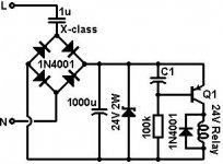
Here's another delay circuit which runs of the mains rather than the heater. Delay time is set by C1 ad is approximately 0.5 seconds per 100uF. The zener should have the same voltage as the relay coil. Obviously it is not 'intellegent' in that it only activates when the power is first applied, it doesn't detect faults or owt like that. Just thought I'd add it to this thread's collection!
Attachments
- Status
- This old topic is closed. If you want to reopen this topic, contact a moderator using the "Report Post" button.
- Home
- Amplifiers
- Tubes / Valves
- B+ time delay relay