Hi Everyone,
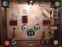
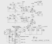
Here is were I need major help, understanding the schematic to wire this baby up. I'll post a pic of schematic and pic of what it looks like underneath. Where would one start? Also, where should I put a star ground? Thanks for the help and there will be a ton of posts in this thread, so please check back often. Thank you!!!
Here is were I need major help, understanding the schematic to wire this baby up. I'll post a pic of schematic and pic of what it looks like underneath. Where would one start? Also, where should I put a star ground? Thanks for the help and there will be a ton of posts in this thread, so please check back often. Thank you!!!
Attachments
WIRING
Hi,
Make sure you have the socket layout for the tubes at hand.
Take a copy of your diagram and add the pin numbers of these sockets on it.
Also take note of the colourcoding of the transformer and add this to this copy as well.
Then you can start with heater wiring as Tomatito suggests,than the B+ from the 5U4 to the caps and choke.
From there you can add the anode and cathode resistors for the 6SN7.
Connect B+ (390V on the diagram) to the second half of the 6SN7,
the 36K 1W resistor from that point to the anode resistor of the first half of the 6SN7.
Add the bypass cap to the anode resistor.
Connect the B+ (405V) to the OPT and wire the other end to the anode of the 300B.
Solder the B+ resistor (1k8/3W) in series after the first filtercap and the 100K in paralel (this one needs to be grounded,see below) after the choke.
Connect the trimpot,cathode resistors and bypass cap (watch polarity) for the 300B heater.
Solder the 470R gridstopper as close to the grid of the 300B,the bias resisitor (220K) can share the same solder eyelet.
On the second half of the 6SN7 add the cathode bypass cap (100microF/?),again watch polarity.
You can now hook up the input,volpot and its' output to the grid of the first tube making sure to connect to G1.
Jumper the anode of the first half to the grid of the second tube.
From the anode of the second half you can now solder in the coupling cap to the gridresistor of the 300B.
On the diagram you will see a grounding point at the first cathode resistor and one at the 300B cathode resistor.
You can wire the ground from the RCA connector to the cathode resistor end,add the endwires from the second half of the 6SN7 cathode resistor and bypass cap towards this point.
Make a separate groundpoint at the 300B cathode resistor and solder there to ground.
A third groundpoint is required for the bypass cap at the first anode resistor.
Another one is to be made at the PSU end where you see the 100K/2W bleeder resistor.
As far as I'm concerned groundpoint 3 and 4 can share the same connection provided it is done at the PSU side.
Make sure any unused transformer leads are individually insulated and not touching the chassis.
Visually check for anything forgotten (me or you") ) and you can now put in the tubes and fire up the amp.
) and you can now put in the tubes and fire up the amp.
Actually soldering on the tube sockets is often easier with the tubes in place but I think your sockets are special ones that don't move when you solder on the pins hence...
From what I see you're building these amps as monoblocks,so don't be surprised to measure a too high B+.
This will require adjustment later on especially since the 6SN7 is direct coupled.
Unless you use a different xformer of course.
BTW,I see a UX5 socket as well,is this for measuring purposes?
May I ask fellow members to correct me if I made mistakes or have overlooked something.
Cheers,
Hi,
Make sure you have the socket layout for the tubes at hand.
Take a copy of your diagram and add the pin numbers of these sockets on it.
Also take note of the colourcoding of the transformer and add this to this copy as well.
Then you can start with heater wiring as Tomatito suggests,than the B+ from the 5U4 to the caps and choke.
From there you can add the anode and cathode resistors for the 6SN7.
Connect B+ (390V on the diagram) to the second half of the 6SN7,
the 36K 1W resistor from that point to the anode resistor of the first half of the 6SN7.
Add the bypass cap to the anode resistor.
Connect the B+ (405V) to the OPT and wire the other end to the anode of the 300B.
Solder the B+ resistor (1k8/3W) in series after the first filtercap and the 100K in paralel (this one needs to be grounded,see below) after the choke.
Connect the trimpot,cathode resistors and bypass cap (watch polarity) for the 300B heater.
Solder the 470R gridstopper as close to the grid of the 300B,the bias resisitor (220K) can share the same solder eyelet.
On the second half of the 6SN7 add the cathode bypass cap (100microF/?),again watch polarity.
You can now hook up the input,volpot and its' output to the grid of the first tube making sure to connect to G1.
Jumper the anode of the first half to the grid of the second tube.
From the anode of the second half you can now solder in the coupling cap to the gridresistor of the 300B.
On the diagram you will see a grounding point at the first cathode resistor and one at the 300B cathode resistor.
You can wire the ground from the RCA connector to the cathode resistor end,add the endwires from the second half of the 6SN7 cathode resistor and bypass cap towards this point.
Make a separate groundpoint at the 300B cathode resistor and solder there to ground.
A third groundpoint is required for the bypass cap at the first anode resistor.
Another one is to be made at the PSU end where you see the 100K/2W bleeder resistor.
As far as I'm concerned groundpoint 3 and 4 can share the same connection provided it is done at the PSU side.
Make sure any unused transformer leads are individually insulated and not touching the chassis.
Visually check for anything forgotten (me or you
) and you can now put in the tubes and fire up the amp.Actually soldering on the tube sockets is often easier with the tubes in place but I think your sockets are special ones that don't move when you solder on the pins hence...
From what I see you're building these amps as monoblocks,so don't be surprised to measure a too high B+.
This will require adjustment later on especially since the 6SN7 is direct coupled.
Unless you use a different xformer of course.
BTW,I see a UX5 socket as well,is this for measuring purposes?
May I ask fellow members to correct me if I made mistakes or have overlooked something.
Cheers,
76
Ho,
Thanks Maarten.
I also forgot to state the obvious:the power on switch as to be wired up as well of course and the amp meter and LS posts.
Also in this case it would be a good idea to wire the 6SN7 on one of the monoblocks so it uses the second half of the tube.
That will allow for more useful life of these since you can than swap them after a couple of years use.
Cheers,
Hello and Merry Christmas,
Questions:
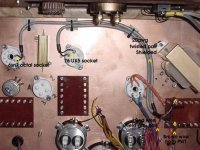
1. 6sn7, 76 tube. Connected the filament wire (6.3v 4a) wire from the power transformer to the turret board, one wire to each side. Then I took two shield wires, two 20awg leads each/w ground leads, soldered them to the turrets, running them to each tube filament, Is polarity a concern to be followed for a/c filament heaters? Also, where should the ground wire for the shields be soldered?
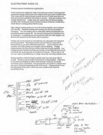
2. The power transformer filament tap for the 300b is 7.2v 1.5a and is to be rectified to achieve the needed 5V. 1.5a. I purchased 8 schottky barrier diodes from DigiKey, rated at 20v 16a. They are dual rectifiers. The part number is SR1602-ND http://dkc3.digikey.com/PDF/T023/V5/0491.pdf . They are in TO-220 packages. They have three leads coming out with these symbols (~ + ~). I hope I can use these and how do I hook them together to rectify the signal? I have heat sinks for them also. I’ll post a picture of the schematic from Electra Print.
Thanks again very much for any help
Questions:
1. 6sn7, 76 tube. Connected the filament wire (6.3v 4a) wire from the power transformer to the turret board, one wire to each side. Then I took two shield wires, two 20awg leads each/w ground leads, soldered them to the turrets, running them to each tube filament, Is polarity a concern to be followed for a/c filament heaters? Also, where should the ground wire for the shields be soldered?
2. The power transformer filament tap for the 300b is 7.2v 1.5a and is to be rectified to achieve the needed 5V. 1.5a. I purchased 8 schottky barrier diodes from DigiKey, rated at 20v 16a. They are dual rectifiers. The part number is SR1602-ND http://dkc3.digikey.com/PDF/T023/V5/0491.pdf . They are in TO-220 packages. They have three leads coming out with these symbols (~ + ~). I hope I can use these and how do I hook them together to rectify the signal? I have heat sinks for them also. I’ll post a picture of the schematic from Electra Print.
Thanks again very much for any help
Attachments
QQQ
Paul,
What did you use the turret tag board for?
Why shielded wires?
Just twist them.Polarity doesn't matter.
If the leadouts from the transformer are too short just solder the same gauge to them so you reach the tube sockets directly.
Don't use the turrest boards for this.
Cheers,
Paul,
Then I took two shield wires, two 20awg leads each/w ground leads, soldered them to the turrets, running them to each tube filament,
What did you use the turret tag board for?
Then I took two shield wires, two 20awg leads each/w ground leads, soldered them to the turrets, running them to each tube filament, Is polarity a concern to be followed for a/c filament heaters? Also, where should the ground wire for the shields be soldered?
Why shielded wires?
Just twist them.Polarity doesn't matter.
If the leadouts from the transformer are too short just solder the same gauge to them so you reach the tube sockets directly.
Don't use the turrest boards for this.
Cheers,
Not normally, though a switchover once the amp is completed, might make a tiny change in signal-to-noise.Is polarity a concern to be followed for a/c filament heaters?
Unless directed otherwise, take them to the central earthing point. Ground only one end.Also, where should the ground wire for the shields be soldered?
Rectifiers:
Ah, how many did you buy?They have three leads coming out with these symbols (~ + ~). I hope I can use these and how do I hook them together to rectify the signal?
If you bought 4, that's fine. Parallel the outer pins.
If you bought 2, it becomes more complex: One is suitable for the "top" end of the bridge, but you'll need another 2, or a different configuration of rectifer for the bottom. IMO it's better to use 4.
Heatsinking:
Your chassis is the best heatsink for miles. If there is a way of attaching them to the chassis - do it. If the tab is metal, it'll need an isolating kit. Some have plastic coated tabs; they're easiest.
SHIELDED HEATER WIRES???
John,
Shielded heater wires???
No,better to get them as far away as possible from anything else so don't use the turret boards for that.
IMO,you don't even need any of those turret boards anyway.
Why did I write up all these soldering instructions anyway?
Good thing it's X-mass,
John,
Unless directed otherwise, take them to the central earthing point. Ground only one end.
Shielded heater wires???
No,better to get them as far away as possible from anything else so don't use the turret boards for that.
IMO,you don't even need any of those turret boards anyway.
Why did I write up all these soldering instructions anyway?
Good thing it's X-mass,
I'm at work.P.S.What's on the menu?
No food of interest.
A colleague brought in some Belgian beer.
I've just finished a Malheur (10%), she's just had a La Trappe (8%). Lucky we've got no more.
Hi Frank,
Thank you for help, now and in the future. I am not trying to be difficult ,please remember I am new here and I am learning as fast as I can. Here is a labeled pic of what I did. There are two 20awg twisted wires in each shield. The shield is teflon wrapped, ground wire soldered on one end of each shield. If you really think the turret is a bad idea, would you please explain why? I will change if needed, nothing is in stone.
Hi dhaen,
I have eight diodes, would it be possible to see a diagram of how the connections should be made?
~ + ~-------) to choke
| |
~ + ~-------) to ground
Really guessing here, I am not an electronics wizard, I am new here and to DIY electronics.
Attachments
TURRET TAGS.
Hi,
No,I don't have anything against turret tags or strips as such,quite to the contrary.
My word of caution was that it is better not to use these for heater wire supports as you effectivelily lift the wiring away from the chassis.
Secondly there is also the risk of radiation of the heater wires into
other components you may have to solder in close proximity of them.
(hum pick-up).
Also there is no need to go overboard by shielding the twisted pair of heater wires as you do IMO.
I never tried it as I never felt the need for that arrangement,simply carefully laying them out won't cause any hum.
But,you have the benefit of the doubt,if it works well then why not?
If I were to use shielded twisted pairs as you do I would not ground the shield at on of the heater wires (the shiled now carries AC as well) but just ground the shield to chassis ground at the tube side.
Cheers,
Hi,
If you really think the turret is a bad idea, would you please explain why? I will change if needed, nothing is in stone.
No,I don't have anything against turret tags or strips as such,quite to the contrary.
My word of caution was that it is better not to use these for heater wire supports as you effectivelily lift the wiring away from the chassis.
Secondly there is also the risk of radiation of the heater wires into
other components you may have to solder in close proximity of them.
(hum pick-up).
Also there is no need to go overboard by shielding the twisted pair of heater wires as you do IMO.
I never tried it as I never felt the need for that arrangement,simply carefully laying them out won't cause any hum.
But,you have the benefit of the doubt,if it works well then why not?
If I were to use shielded twisted pairs as you do I would not ground the shield at on of the heater wires (the shiled now carries AC as well) but just ground the shield to chassis ground at the tube side.
Cheers,
- Status
- This old topic is closed. If you want to reopen this topic, contact a moderator using the "Report Post" button.
- Home
- Amplifiers
- Tubes / Valves
- JE Labs 300b round 4. Wiring, HELP!!!