Hi Alastair,
You should have mail Thanks again for your kind offer.
By the way, I love the way this thread is developing!
I'm sure there must be others out there like me who are wary of the usual high voltage stuff but would love to play with valves. I know that I have the knowledge to build a power supply for, say 80 Volts or so but need projects like these as stepping stones. Mains scares me!
I do have one other valve circuit around which is a guitar overdrive using a 12AX7. I haven't dared to open it up yet because I knew that I'd probably break it! I will soon, but I know that it changes the 12V supply to 24V.
I've been checking Ebay for Nuvistors. It's funny that the sockets cost more than the tubes!! Interesting looking things though.
Thanks for the inspiration,
Martin.
You should have mail
Thanks again for your kind offer. By the way, I love the way this thread is developing!
I'm sure there must be others out there like me who are wary of the usual high voltage stuff but would love to play with valves. I know that I have the knowledge to build a power supply for, say 80 Volts or so but need projects like these as stepping stones. Mains scares me!
I do have one other valve circuit around which is a guitar overdrive using a 12AX7. I haven't dared to open it up yet because I knew that I'd probably break it! I will soon, but I know that it changes the 12V supply to 24V.
I've been checking Ebay for Nuvistors. It's funny that the sockets cost more than the tubes!! Interesting looking things though.
Thanks for the inspiration,
Martin.
Mail and Nuvistors.
Yes, the sockets can be an issue, but best thing to do, is keep an eye out on fleabay, sometimes they can go quite cheaply....
I have your address, and Ill post out the 6H8C (6SN7 clone) on Monday, You should get it in a day or two...
For low volts operation, the medium Mu types like the 6DJ8, 5687 6SN7 Ive found to be the most suitable, along with the 7586 Nuvistor...
Have a look at Tubelab's website for tips on safety at high voltages. his site is full of other great info on valve circuits as well as his pages devoted to safety, Its all great advice, reminds me of the days when I started out. The first thing I was told was to keep one hand in my pocket when doing any 'live' testing.......
www.tubelab.com
I appreciate your generosity and good advise a lot Alastair, can you perhaps tell me if some of the tubes are more suitable to whitstand the vibrations in a car? I suppose the Nuvistors are good in this aspect?
How much current would a circuit like that draw?
I like Tech's signature here on the forum:"Too much power is almost enough! Turn it up till it explodes- then back up just a little..." ("Tech" from Tubelab...)
Sorry to bother with these questions, but I would most appreciate it if you could forward a good schematic or link to a good circuit....thanks in advance.
How much current would a circuit like that draw?
I like Tech's signature here on the forum:"Too much power is almost enough! Turn it up till it explodes- then back up just a little..."
("Tech" from Tubelab...)Sorry to bother with these questions, but I would most appreciate it if you could forward a good schematic or link to a good circuit....thanks in advance.
It still makes me laugh too! It's so abstract! It's quite hard to fit anything good into a <20Kb file.v-bro said:Sonusthree, I find the avatar most hilarious!
And indeed don't fry thyself!

I custom made this one especially for Burnedfingers but he hasn't used it yet

I would one day hope to have a decent valve power amp. But for now it is better that I am alive!!

Martin.
Attachments

v-bro said:I appreciate your generosity and good advise a lot Alastair, can you perhaps tell me if some of the tubes are more suitable to whitstand the vibrations in a car? I suppose the Nuvistors are good in this aspect?
How much current would a circuit like that draw?
I like Tech's signature here on the forum:"Too much power is almost enough! Turn it up till it explodes- then back up just a little..."
Sorry to bother with these questions, but I would most appreciate it if you could forward a good schematic or link to a good circuit....thanks in advance.
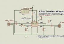
Im afraid The published schematic as you see it on the previous page is all there is--Like most things, its a work in progress and alterations are being done already, to suit my own use for it....
Adapt and modify it for your own needs, Duplicate it for a second-channel etc.etc. I cannot design it for you, as I dont even know to what use you are to put it! Use a 6V 1A linear volt-reg for the 6V heater of the valve. A single 6DJ8 consumes around 300mA so a 1A reg will supply both valve heaters. a single 7586 Nuvistor heater consumes around 130mA
The Anode-current is around half a milliamp per triode (600-700uA) so not even worth mentioning after the heater...
Use a valve such as the 6DJ8 5687 or any medium Mu triode/double-triode--You have Loads to choose from and experiment with....
Do what they used to do years ago with valves in harsh environments and car radios and use a shock absorbing frame/box/mountings, holding/containing the valves...
A tip--- Russian Nuvistors are far superior to American nuvistors with regards microphonics etc, and tend to be cheaper too.......
There isnt much on the 'web it seems about running 'Standard' type valves at low-voltage. There are some valves that were made specifically for low-volts, but could be hard to come by...
Hmmm, confusing...I didn't notice your post#40 Alastair, so I didn't even mean to criticize the previously posted circuit..
I should follow your advise to read better before I post....
I have to admit I'm quite a noob on tubes....so would it be better to consider a step-up from 12V to say 35V rails? I have a dual supply that can deliver, perhaps even with a class D (T) power stage on the same supply? As it doesn't need a lot of current, and the supply delivers dual 35V at about 6A...
Considering the valves can be hard to get by, increasing the voltage might offer new possibilities...
Still I would love to see the tubalizer do the job ....
They used to sell a complete integrated amp with a tube inside (still visible on the audiodigit mainpage picture), but it's not on the shop page anymore....Wonder what circuit they used in there....
v-bro said:Hmmm, confusing...I didn't notice your post#40 Alastair, so I didn't even mean to criticize the previously posted circuit..
I should follow your advise to read better before I post....
I have to admit I'm quite a noob on tubes....so would it be better to consider a step-up from 12V to say 35V rails? I have a dual supply that can deliver, perhaps even with a class D (T) power stage on the same supply? As it doesn't need a lot of current, and the supply delivers dual 35V at about 6A...
Considering the valves can be hard to get by, increasing the voltage might offer new possibilities...
Still I would love to see the tubalizer do the job ....
They used to sell a complete integrated amp with a tube inside (still visible on the audiodigit mainpage picture), but it's not on the shop page anymore....Wonder what circuit they used in there....
It would definately improve the headroom, but as designed, I taylored it for a supply of just 12V.....
Ive not tried it at higher +B yet, Something I could try is say, 24V Easy enough, I have a couple of SLA's....
All the valves Ive mentioned are reasonably easy to come by, so no probems there either--They are just the 'usual-suspects' in valve audio.....
I did a quick Simulator test for the 6DJ8/ECC88 at 24V and at 36V, The current through the valve increases to a little over 1 mA for each triode half and nearly 2 mA at 36V...All to the good. At 36V it needs a 3V RMS (Approx 9V P-P) signal to drive it to clipping, at a voltage output of just under 35VP-P--Doubt that as a 'line-amp' you would ever get near that level!...
v-bro said:I like the simplicity of the schematic, I think will order some tubes soon...and first listen to what happens on 12V...
Thank you very very much Alastair, I'll post here on my progress or when I'm done...
I just tried the scheme as drawn on 24V. Apart from a slight increase in gain, there was no other apparent audible effect. As another contributor here said, this is due to the large amount of Local Neg feedback in each stage. (The grid-resistor returned to the Cathode rather than deck, and a fairly large cathode resistor in the gain stage...)
The available Headroom at 24V is of course doubled, great if you have 24V supplies commonly found in SS amps, and fancy adding a little valve pre-amp to....
I do have an SMPS that delivers 2x 24V (+ and -) from 12Vdc. It can deliver about 4A....
Would this work when I use two bufferstages (one for each channel)?
I also have two 24V four channel amps...
Only problem is the amps suffer from a ground loop somewhere, when I connect them both to the same supply I get a whining/whistling kind of noise that responds on the gaspedal...(when I connect one amp to a separate battery the noise goes away...) I probably need to add some kind of filter, or perhaps the SMPS will filter it....will soon test this...
So would adding a preamp stage as well provide more overall gain? Or would I just blast the line inputs of my amp? It is protected with zenerdiodes on the input, and remember an occasion where the overload led responded with only my mp3 player connected. So I really wonder how much improvement there is to be 'gained' ...
Would this work when I use two bufferstages (one for each channel)?
I also have two 24V four channel amps...
Only problem is the amps suffer from a ground loop somewhere, when I connect them both to the same supply I get a whining/whistling kind of noise that responds on the gaspedal...(when I connect one amp to a separate battery the noise goes away...) I probably need to add some kind of filter, or perhaps the SMPS will filter it....will soon test this...
So would adding a preamp stage as well provide more overall gain? Or would I just blast the line inputs of my amp? It is protected with zenerdiodes on the input, and remember an occasion where the overload led responded with only my mp3 player connected.
So I really wonder how much improvement there is to be 'gained' ...I guess the whine on the vehicle batt. is caused by the alternator charging circuit....
You may need a filter fitted at the alternator end. Sometimes a 1 mic cap accross the main alt to deck will cure it, sometimes a proper filter is needed...
You can use a common supply for both channels of the valve circuit, just like you would with most pre-amps. You could separately decouple the supplies with an R-C filter but shouldnt really be needed, although you would need a good filter from the supply if it is in any way 'noisy'...
The valve circuit will give you more gain. However, it all depends on your other devices as to whether it will be beneficial or maybe then just too much gain so the MP3 player vol setting is right down and yet the amp is driven to full O/P....
Alastair E said:You may need a filter fitted at the alternator end. Sometimes a 1 mic cap accross the main alt to deck will cure it, sometimes a proper filter is needed...
You mean just like a buffer electrolitic cap, to get rid of any ripple? I'm afraid it will need a better filter than that.... I think it does come from the alternator, but one amp is no problem, with the second amp the noise appears when I either connect both inputs or both power lines together....
Alastair E said:
You can use a common supply for both channels of the valve circuit, just like you would with most pre-amps. You could separately decouple the supplies with an R-C filter but shouldnt really be needed, although you would need a good filter from the supply if it is in any way 'noisy'...
So where would be best to place an R/C filter? And what x-over freq. should it be designed for? I suppose a large coil in series with a large cap in parallel with the dc power line should suffice keeping any ac noise out of the dc, right? Or should I also add a coil in the ground line?
I did stumble upon some car audio filters (against ground loop hum...) on the internet, but I can't find any information on what's inside.....
Alastair, Happy St David's Day (for yesterday).
I received the 6SN7 yesterday. Your amazing generosity and is very much appreciated. I cannot thank you enough.
It is undoubtedly better suited to this circuit than the 6SL7. There is less distortion in listening tests but unfortunately it is still there on the louder passages.
I have changed the grid bias and cathode resistors.
Shorting the resistor before the potentiometer gives the most usable range and the ability to reduce the resistance until the point where the sound stops. The voltage measured between negative supply and the output ground (RCA Jacks) is -6 volts when the the cathode load resistance is ~50K.
With the 6SN7 I have heard the potential of tube circuits in my system. It has definitely given a more 'valve' sound except for the distortion. I spent a few hours last night enjoying a jazz compilation. This has a huge (for CD) dynamic range and therefore does not distort for most of the time. Most other C.D.'s distort.
How on earth is this circuit supposed to work?
I believe that the tubalizer cannot handle regular line level sources. There is just not enough headroom with this B+. I have changed the Grid bias resistors to compensate but, in the end, what is the point of having a line level buffer with an input impedance of <10KOhms?
Any compressed types of music are just not listenable, so that excludes most modern disks.
The heater reg is a lot hotter than before. It's too hot to touch the heatsink for more than a second. The 6SN7 runs a bit hotter too and glows more than the 6SL7. I'm really seduced by it's appearance at night. I know this is not what tubes are for but their beauty really appeals to me.
My next step is to hook the whole thing up to the soundcard again and get some waveforms on the screen to see how it differs from the 6SL7.
I will post again soon with further results.
My options are now:
1, Send the Tubalizer back and try for a refund.
2, Alter the circuit to run on 24V.
3, Try attenuating the signal before the Tubalizer.
Regards,
Martin.
Im glad it turned up in one-piece and does help out the issue, but there is obviously still something serious wrong.....
As a test, remove the two grid-resistors, and place them between pins 1-3 and 4-6. of the valve......
IF your second diagram IS correct, these resistors are effectively going to no-where DC wise....They are De-Coupled by an elect. cap back to the neg line, hence no DC route to neg line, so little or no grid-leak, apart from that through an electrolytic cap....
Placing them directly at the valve-pins will at least give the valve some grid-bias, as well as neg-feedback to help out with the distortion, and is the way that the 'cathode-follower' stage works in my 'tubaliser' diagram I posted earlier...
It may be worth lowering the value to around 33K as well, maybe lower, for best operation--Dont worry about the input-impedance, as when connected this way, they are 'bootstrapped' so will not present their real value to the input, The value 'seen' at the input will be an order of magnitude higher.....
Alternatively, you could 'knock-up' that version of the tubaliser that I posted, using whatever old parts and junk you have around just to confirm to yourself that a valve will work at very low volts. It might be a fun way to start out
Octal valve-sockets are often used for relays and the like, You should be able to find one fairly easily Try an electrical-factors, the sort of place that supplies the electricians in your area ....Very old electromechanical fruit machines have loads of plug-in 50V relays and loads of octal-sockets......
Thanks yet again Alastair
I was just sitting here and making plans to raise the B+ and remove the reg from the board to enable this. You have just given me another option.
I'll be back soon with the results!
I am already collecting the parts. I can't wait. But, what's the difference between international, British and Mazda octal sockets?
I suspect that only Mazda sockets are unsuitable for regular valves but am not entirely sure. Can anyone put me out of my misery?
Kind regards,
Martin.
I was just sitting here and making plans to raise the B+ and remove the reg from the board to enable this. You have just given me another option.
I'll be back soon with the results!
Alastair E said:Alternatively, you could 'knock-up' that version of the tubaliser that I posted, using whatever old parts and junk you have around just to confirm to yourself that a valve will work at very low volts. It might be a fun way to start out
Octal valve-sockets are often used for relays and the like, You should be able to find one fairly easily Try an electrical-factors, the sort of place that supplies the electricians in your area ....Very old electromechanical fruit machines have loads of plug-in 50V relays and loads of octal-sockets......
I am already collecting the parts.
I can't wait. But, what's the difference between international, British and Mazda octal sockets? I suspect that only Mazda sockets are unsuitable for regular valves but am not entirely sure. Can anyone put me out of my misery?
Kind regards,
Martin.
Found this rather interesting:
http://www.diyparadise.com/simplepreamp.html
I sent an email to a nos tubes supplier, the 5687 would be from Philips USA and cost is 14 EUR. 5 EUR. to match a set and 9.50 EUR. to send (if I remember correctly).
Here:
http://www.analogueaudio.com/buizen.htm
http://www.diyparadise.com/simplepreamp.html
I sent an email to a nos tubes supplier, the 5687 would be from Philips USA and cost is 14 EUR. 5 EUR. to match a set and 9.50 EUR. to send (if I remember correctly).
Here:
http://www.analogueaudio.com/buizen.htm
5687
Personally, I dont use those 'tube-dealers'....
For me, they are just too expensive. I get job-lots of say, 5 valves off fleabay, often NOS, in original boxes and for the same price you would pay for a single tube from one of those dealers!
For Pre-amp work, I wouldnt even think of 'matching' as tubes drift as they age within the first 200 odd hours anyway and will age/mis-match at different rates. I very much doubt you would hear any difference in a matched to un-matched pair in a well designed circuit
Just use the same make/age of tube in each channel....
- Home
- Amplifiers
- Tubes / Valves
- 6SL7 or 6SL7GT for broken Tubalizer