For the tube to work, it must conduct current....
For it to work with little or negligable distortion, it must conduct All the time the signal swings, ie, Class A....
Whats happening I believe is that its only conducting during one-half cycle, the other being cut-off, as there isnt sufficient 'headroom' or current flowing through the valve in the first-place....
Why one-half-cycle?....
Its to do with the way the tube is biassed I believe... During positive half-cycles, this is adding to the grid, a positive potential greater than its standing no signal set value, which causes the valve to conduct more current...No problem so far....
But when the neg half cycle comes along, and as the valve isnt conducting much in its 'standing' no-signal state, it drives the grid sufficiently negative to completely cut off current flow all together...
This is why it appears to 'work' with Very low signal levels on its input, There is just sufficient current flowing to allow very small signal operation
The result is the loss of the half cycle you can see when more 'normal' signal levels are used....
The cause?--
Not enough supply volts to the tube, or its operating point is chosen badly with insufficient current being passed in its 'standing' or no signal state, This second point probably caused by the first point!...
What value is the resistor network on the grid, and what potential do you read at the grid in relation to the cathode?
At a wild guess, to work at all it must have a positive potential at the grid in relation to the cathode or I would doubt a 6SL7 would conduct any current at all at 12v!
We really need the 'schematic' and some voltage readings would be interesting to see what the supplier is trying to do....,
Thanks to everyone for your help so far.
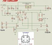
I have draughted a schematic. It needs a lot of tidying up and a proper tube diagram in the middle instead of the pins but I thought that I'd throw this out there for an initial response.
The values are a little hard to read at the moment. Sorry.
I will add a final and more legible version soon...........
Any hints as to how this thing is working and also what the fault could be?
Regards,
Martin.
Edit: Please ignore the polarity of the electrolytic caps if I have got them reversed by mistake!! (It's very late here.)
Attachments
Hi Sonusthree ,
Anything wrong with your schematics !!!
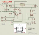
The 6 Volts regulator’s ground , NEEDS to be
connected to the ground , if not , the regulator
will “float” and the output will not be 6 Volts .
Pin 2 and pin 5 are tied to ..... ???
Please , verify all stuff again . Thanks .
Carlos
Anything wrong with your schematics !!!
The 6 Volts regulator’s ground , NEEDS to be
connected to the ground , if not , the regulator
will “float” and the output will not be 6 Volts .
Pin 2 and pin 5 are tied to ..... ???
Please , verify all stuff again . Thanks .
Carlos
Sonusthree said:Darn it!! I need to check where the B+ is coming from but I would assume it's simply the full 12 Volts.
Sorry for the silly mistakes but it was very late when I finished it and I am still learning all the time.refference said:The 6 Volts regulator’s ground , NEEDS to be
connected to the ground ...............
Pin 2 and pin 5 are tied to ..... ???.
")
Here is the revised schematic. There may still be some errors but I think it is correct now.
Cheers,
Martin.
Attachments
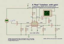
Hmm, Looks like a pair of cathode-followers, with a variable cathode load....
Varying the cathode-load will change the op. point and also increase/decrease its distortion and out-put impedance I believe....
Out of interest and because of this thread, Ive delved into low volts tube stuff and come up with a scheme Ill post later..At work currently, nothing interesting here!
Ive chosen a different valve to your 6SL7g/gt, Ive used the cheap and chearful computer triode 5687, which is a very popular pre-amp driver and has developed quite a following in the DIY 'scene'...
I chose this as it has a 6 and 12V heater option and very high 'pervayence' My little experiment has a gain-stage followed by cathode-follower O/P.-- Works well providing you keep its input below 800mV P-P or it will clip, otherwise its sound is fairly neutral.--It has a gain of around 10 ish, currently...
The Tubaliser scheme will have a negative gain of around .8 ish....
If I get the time, Ill play with the 6SL7 in the same scheme and tweak values to suit...
For the purposes of your 'Simulation' work, choose the ECC83 or 12AX7 in Proteus, while not the same as the SL7 its similar enough to work out whats happening, seeing you have such a 'drastic' fault...
I used the ECC88 for my 'sim' work in Proteus before building the breadboard with the 5687. It was similar enough at low volts to work out OK...
(To be quite honest, Its the first time Ive used the 'Simulator' in Proteus....!)
Alastair, I cannot thank you enough.
I chucked a 12AX7 into the sim and was able to see what is happening. I will, tonight, change all of the resistors in the software for realtime potentiometers. Why not?
I am a complete tube noob and this experience has been most enlightening. I know understand the biasing mechanism involved here. From the simulator (and your advice) I can see that it is a little 'off centre'. I believe that increasing the resistors around the 50K pot is the solution.
Please correct me if I'm wrong. I hope I'm not.
This theory also matches my experiences. When turning the pot clockwise (increasing resistance) the treble opens up and the distortion lessens. Turn it anti-clockwise and the treble goes and distortion increases.
Theoretically: 52K of resistance still distorts so I should probably try swapping the resistors (2.26K) for ~ 27K. If this works then I will perfect this value to give the most usable range with the pot.
The simulation seems rather inaccurate with regards to input amplitude and resulting gain but I'll just have to try it in the real world.
I will report back later.
Thanks again, and wish me luck.......
Martin.
Looked at your scheme again having delved into my own experiments....I was going to try a 6SL7 and 6SN7 in my scheme to see what would happen, but my soldering-iron has quit this life...Typical!
The 'Grid-Bias' resistors in your machine are 220K....
Ive found that at low volts, that the grid-bias resistors need to be below 100K for a good op point. I settled for 47K in my experiments.
Usual values for 'Normal' high-volts operation are around 1 to 2 Meg-Ohms...
The Proteus simulator will still 'say' it works without the grid-resistors in place, but it won't in the real-world, so treat everything in the sim with a little contempt........
If you increase the cathode-load resistance as you plan, this will reduce the amount of available current through the valve, ....At 12V, this is really a very tiny current already....
In my set-up, its just a couple of hundred Micro-amps, and that is with a valve that has comparatively Massive cathodes in comparison to the SL7, so huge area for electron-emission!....
With a 6SL7, and above 50 odd K cathode-load, I would be surprised if you got a few tens of micro-amps Your O/P impedance will also increase if you add resistance here-Not so good, H/F response could well suffer ...
Instead of adding resistance there, try putting a couple of 100K resistors accross the original 220K R6 and R5 grid-resistors rather than increasing the cathode-load. These resistors are'nt 'bootstrapped', as in my layout so will affect the input impedance a little but shouldnt be noticable unless you have a very high O/P impedance of your source-device (Very unlikely!)
If this helps, try going lower, say down to 60 odd K....At least this will increase the current through the valve without increasing its O/P impedance. The cathode voltage can be measured which will give you an idea of the current flow.......
Even if you were to place a short here, at 12V you wont damage the valve, as its normal HV operation it passes around 2-3mA...You will not get anywhere near that amount of current at 12V, so feel free to mess around there all you like!
Right, Now Im gonna try and copy out the scheme of my 12V amp and post it here... Ill add real-world voltage values at various places for interest--Im currently playing the TV sound through this bread-board and my OTL.....
Update: My 4 week old soldering iron is starting to melt (plastic handle) and hiss. Not good!
I have just changed the 2.26K cathode load resistors to 30K (before I read this). Less distortion than before but still not completely gone. The pot now has less effect on the sound. I need to analyse the output on my soundcard to see what effect this has had.
The manufacturer once advised me to use 33K - 47K resistors in parallel with the 'Grid-Bias'. This helped but did not cure the problem. In the end I added a stereo pot across these resistors. The distortion lessened with resistance but never went entirely. At very low R, the low frequencies would begin to fade rapidly just as the clipping was!!!
I guess that I should probably adjust the 'Grid-Bias' resistors to the lowest possible before the L.F. response fades. and then try raising the 'cathode load' slightly.
Darn!!! My simulation seemed to indicate that increasing the cathode load was a good idea. How naive am I?
Could it be a combination of two or more things?
I'll be back with more results!!
Martin.
More confusion!
This tubaliser thing Must work, or they wouldnt sell the thing....
The more I look, think and sim out (Even more confusing as its not really 'right' in Proteus for valves it seems...) the more i come to the conclusion that the SL7 Isnt really suitable...But they sell it With a SL7, so it must work with it....
Will get new iron tomorrow, and hopefully play tomorrow night....
It's hooked up to my soundcard now and I'm going to mess around for a while and see what I can do.
Thanks for posting your version of the Tubalizer Alastair. It's really helping my mood right now. Who needs gain anyway?
Maybe the people who like this Tubalizer use it after the volume pot as a kind of passive/active pre/buffer? When they turn it up they think their amp is clippping?
I'll be very interested in low voltage valve circuits in the future and will probably build yours when I can get the parts. I know nothing about valves really but where does the 88.8Volts come from on your schematic?
Cheers,
Martin.
Thanks for posting your version of the Tubalizer Alastair. It's really helping my mood right now.
Who needs gain anyway? Maybe the people who like this Tubalizer use it after the volume pot as a kind of passive/active pre/buffer? When they turn it up they think their amp is clippping?
I'll be very interested in low voltage valve circuits in the future and will probably build yours when I can get the parts. I know nothing about valves really but where does the 88.8Volts come from on your schematic?
Cheers,
Martin.
Hi Martin,
the 'Voltmeter' in the scheme was part of the 'simulator' and is just a graphic, as is the 'scope. It doesnt actually read a voltage untill you run the simulator, and ask it to where it then opens a dialog box with the true readings in.--Same with the 'scope, untill you run the sim, its just a graphic........
One thing that did occur to me, is that the device/amp you are playing this thing into could have an unusually low I/P impedance which could be loading the valve too much...Just a wild stab in the dark....
Even in my breadboard using the 5687, I only pass 470 odd Micro-amps through the gain stage, and 600 odd through the follower, I guess the SL7 would be less by a factor of ten...Not much current to load down!
I know some sound-cards have rediulously low I/P impedances especially on their 'mic' sockets, due to the 'phantom' suppy rail for electret type mics...
One thing that I really quite like about this Low Voltage valve experiments, is you can use any old parts culled out of equipment or 'Scratch-Box' and not worry about its voltage-rating....No Need for special high-voltage poly-props or leccys, just about any old parts will work for experimenting!
More info....
Got a new iron and soldered in a nice Octal socket accross the 9 pin in there....
Interesting findings with a variety of different types...
First, a 6SL7GTB, Geny elect. make, coin base from mid 80's....
Wont work at all, The cathode-follower stage shows some life, but nothing from the gain-stage...(Not sure why, it works just fine at proper voltages.....)
Second, a Russian 6H9C (6SL7 clone) from the mid 70's
This valve does work, but with audible distortion. There is only .7V accross the cathode follower resistor....
Next, a 15-79 (Another Russian SL7 clone for heavy duty use allegedly)
This valve worked better than the 'standard' Russian SL7, but still had audible distortion. There is .8V accross the cathode resistor
Last of my '6SL7' types, a Sylvania 6SL7G from 1943 JAN stock,
This valve worked the best of the SL7 types, but still had some audible distortion noticable in places.....
Next, I tried a 6H8S (A Russian 6SN7 clone) This performed very well with no noticable distortion, good deep bass and clear defined top.
There was 4V accross the cathode-follower resistor with this valve, indicating much higher current flow through the valve.
Now to the 9 pin types....
First we know, the 5687 works well...
Next, a S/H Philips 6DJ8, This worked extremely well almost indistinguisable from the 5687. Not much surprise there, as the current through it was only just a little less than the 5687.
Next, a Mazda 6/30L2 This also performed pretty well, but seemed to 'lack' something....The current through it was also slightly lower than the 6DJ8, by a volt or so accross the resistor at 5V.....
A 12AT7 was tried, but didnt sound very good at all, similar readings and distortion to the SL7 valves, ....
A 6H2P-EB (Russian 12AT7 type, ish) This performed better than the 12AT7, but showed its limited current pass on 'loud' sections..
Im currently running the Octal 6SN7 Russian valve, which is performing pretty well considering!
I did no circuit or value alterations during this testing, I just changed the valves, everything else stayed the same......
From the above experiments, I would suggest that you try a 6SN7 type, direct replacement for the current 6SL7 in your device....
I think it Could cure your issues....
Hi Alastair,
Wow!! You research gives me new hope. I will get hold of a 6SN7 as soon as the girlfriend 'forgets' the supply caps and diodes I just bought for my amp.
In the meantime, I have tweaked the resistors in the present setup to give me an unclipped signal at all frequencies at full line level on my soundcard 'scope. I haven't really had a chance to test it properly on my amp yet but it seems better at least.
You'll probably faint when you hear that the 'Grid-Bias' resistors are ~5K !!! I also reduced the cathode load resistors back down again so that it gave the best adjustment according to my soundcard 'scope. The pot now controls amplitude? and at it's highest resistance distortion starts. I'll list the full values tomorrow when I've checked properly.
You mentioned the amplifier input impedance before as a possible problem. I've tried the device with several amps, mixers and soundcards with the same results. I even breadboarded an opamp buffer to be doubly sure.
Anyway, I bought this thing with the hope that it may become the output stage of my CD player. I'd still like to get it working but will probably use your design . At the very very least I may try the tubalizer with a raised B+.
Thanks Alastair, you have really helped me alot,
Martin.
6sn7
If you Email your address, I can send you a Russian 6SN7, all I ask is that you tell me the results of the test--I have a fair number Ive used over the years for testing Most have only a handfull of hours on them, Just nicely 'Run-In'....
You may well need to add a larger heatsink to the volt-reg, as the SN7 has a higher heater-current than the SL7. Im using a standard 6V 1A reg on a small heatsink from a comp. PSU which is working fairly well in the B.B.
You may need to increase the GB res, back up to say 47K, Something that can only be done in your set-up...Worth trying anyway...
It doesnt really surprise me that the values ended up at 4.7K, It seems you need a very low GB value for any current flow at all at these low +B values...!
Re: 6sn7
Hi Alastair,
That is an amazingly generous offer that will help me a lot. I will send you an email straight away so let me know if it disappears into cyberspace. (Seems to happen quite a lot with forum mail.)
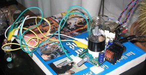
The L7806CV reg. already gets surprisingly hot despite it's large - ish heatsink and my little 'add-ons'. I had the little copper self-adhesive heatsinks lying around and thought I'd attach them to the original. (See pic.)
Latest listening test results are much the same as ever. It's a very uncomfortable feeling waiting for the distortion to appear on the louder passages of your favourite songs.
I've been testing the Tubalizer between my soundcard and C.D player. I'm using a test tone disc and TrueRTA to see what is happening. I have managed to get it performing well with sine waves but NOT with music in my proper setup.
I've tried varying combinations of GB and Cathode load resistance. I have definitely managed to change the characteristics of the distortion but not cure it.
I know very little about valve circuits, yet, but I cannot believe that this circuit would work at all with this 6SL7. Haven't I tried everything except higher B+ or a different type of valve?
I don't know what to think about this whole situation. I get annoyed that this thing doesn't work despite the price tag but I am, conversely, very happy that I have started using valves.
I'm really looking forward to breadboarding some circuits in the future.
Kind regards,
Martin.
Hi Alastair,
That is an amazingly generous offer that will help me a lot. I will send you an email straight away so let me know if it disappears into cyberspace. (Seems to happen quite a lot with forum mail.)
The L7806CV reg. already gets surprisingly hot despite it's large - ish heatsink and my little 'add-ons'. I had the little copper self-adhesive heatsinks lying around and thought I'd attach them to the original. (See pic.)
Latest listening test results are much the same as ever. It's a very uncomfortable feeling waiting for the distortion to appear on the louder passages of your favourite songs.
I've been testing the Tubalizer between my soundcard and C.D player. I'm using a test tone disc and TrueRTA to see what is happening. I have managed to get it performing well with sine waves but NOT with music in my proper setup.
I've tried varying combinations of GB and Cathode load resistance. I have definitely managed to change the characteristics of the distortion but not cure it.
I know very little about valve circuits, yet, but I cannot believe that this circuit would work at all with this 6SL7. Haven't I tried everything except higher B+ or a different type of valve?
I don't know what to think about this whole situation. I get annoyed that this thing doesn't work despite the price tag but I am, conversely, very happy that I have started using valves.
I'm really looking forward to breadboarding some circuits in the future.
Kind regards,
Martin.
Attachments
Looks like the spam filt. got it....Sorry.
Try sending it to, vegoildiesel@yahoo.com
At least Yahoo has a 'Junk-Mail' section so it shouldnt get zapped before I see it!
(Yes, You've guessed it, Im also one of those nutters who runs diesel-engines on veggy oil and make BioDiesel fuel for a living...)
Ive been doing some more potching round with the low-volts circuit I made up.--Its looking rather a mess now with various socket types everywhere! I now have two Nuvistor Triode-valves, The 7586 type (Nuvistors are small metal/ceramic valves, the last development of vacuum tubes)
Ive also altered the scheme slightly to lessen the gain and reduce distortion at high inputs. Ive increased the cathode-resistor of the first-stage to 1.2K and wired the grid-resistor between the grid and cathode connections, instead of directly to deck as before The cathode-follower stage remains the same....
All I can say is that this thing now really rocks! I know Nuvistors were often used at fairly low volts, but usually around 50-90V...They even made a low-voltage type, especially for sub 30V operation the 8056 if I recall correctly.....
My Russian 6C51-HB (7586) Really seem to like this voltage, BRILL sound!--Earthquake bass and perfect airy highs and nothing missing in the middle!
(I did a quick 'sweep-check', and have a fairly flat response from 5Hz to 50 odd KHz)
I never pay much for valves if I can help it, The best place Ive found is on Fleabay believe it to not. You can get some great Russian valves there at peanut prices in comparison to the NOS types from 'Stealers' They work just fine and are brill for experimenting. Most vendors there list the type equivalent so if you do a search on 6DJ8 for instance, youll find all sorts including the Russians....
I plan a small 'line-stage' between an MP3 player and my Class T amp in the car, The MP3, even at its highest volume setting just hasnt the drive for the TA2020-EB board Im using as the amp, and I didnt really fancy meddling with the gain-settings on its I/P stages, as the print on that thing is like tissue-paper
This little Nuvistor based pre-amp now has a gain of around 7 so will be just great for the job!
I must thank you for 'peaking' my interest in doing a Low-Volts line-amp, Its something Ive been meaning to do for a while.....
v-bro said:That's a good thing, would you mind sharing a schematic of this?I use a pretty powerfull (TAA4100A) amp in my car, but still I would like to get a bit more out of my mp3 player...
So is there no glowing light visible from these Nuvistor toobs?

Err, Its on the previous page.....
.Sometimes it pays to read the whole thread....
No glow from Nuvistor....

If you want glow. Use 6DJ8, 5687 etc...
- Home
- Amplifiers
- Tubes / Valves
- 6SL7 or 6SL7GT for broken Tubalizer