6sl7 or 6sl7GT for Broken Tubalizer
Hi everyone,
I have just received an Audiodigit tubalizer that unfortunately isn't very healthy.
http://www.audiodigit.com/?section=81
This is my first experience of valves and hopefully will lead to more adventurous things.
THe Tubalizer is placed between my CD Player and Integrated (14KOhm input impedance) solid state amplifier.
It distorts very badly with any input. It is slightly better with very small signals (-12dB) but not at all satisfactory. I have tried many sources and different power supplies and 'tuning' settings.
I am using a 12v 1.2Amp regulated linear supply with the correct polarity. I have also tried other supplies with no change. My power supply gives 12.06 Volts (unloaded) and the regulator is passing approximately 6 Volts and the tube glows slightly near the top as it should.
I have redone all the soldering to be sure and measured 5.7Volts at the ground of the RCA outputs (This is as it should be.)
This device is only made from a handful of caps and resistors with a 6 Volt regulator and a Sovtek 6SL7.
Surely it must be a faulty Tube? What else could be wrong here? Any help would be very much appreciated. I would eventually like it to be my CD players output device when I get it working.
I feel I should buy a spare valve for test purposes but what is the difference between a 6sl7 and a 6sl7GT?
Please help
Sorry for the long delay.........
I bought this already assembled (only option) from Audiodigit in Italy.
http://www.audiodigit.com/?section=81
I have bought six more (unbranded) 6SL7 and no change.
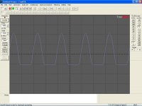
I tried it between a CD player and soundcard and could quite clearly see that the negative cycles were being clipped. The distortion lessens when I reduce the volume on the CD player.
I have emailed the manufacturer and they think that it is probably a combination of bad tube and my amplifiers low input impedance.
I have tried many tubes and amps and have even built an opamp buffer to buffer the buffer!! So, this cannot be the problem.
I am feeding it with a 1250mA 12V regulated linear supply.
I should send it back under warranty but I would like to learn more about tubes and save the hassle of posting and waiting....
The thing that bugs me most is Why does it only clip on the negative cycles?
I bought this already assembled (only option) from Audiodigit in Italy.
http://www.audiodigit.com/?section=81
I have bought six more (unbranded) 6SL7 and no change.
I tried it between a CD player and soundcard and could quite clearly see that the negative cycles were being clipped. The distortion lessens when I reduce the volume on the CD player.
I have emailed the manufacturer and they think that it is probably a combination of bad tube and my amplifiers low input impedance.
I have tried many tubes and amps and have even built an opamp buffer to buffer the buffer!! So, this cannot be the problem.
I am feeding it with a 1250mA 12V regulated linear supply.
I should send it back under warranty but I would like to learn more about tubes and save the hassle of posting and waiting....
The thing that bugs me most is Why does it only clip on the negative cycles?
Attachments
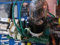
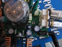
I don't have a schematic but may be able to make my own if it would be helpful. It would be good practise with this double sided board.
The pot at the front is supposed to be "Tube operating point"
Out of view at the back is a 6 Volt reg and heatsink.
The green croc-clips were there to try parallel resistor across the originals. This was advised by the seller. Lowering this resistance does help but lowering too much makes the sound very anaemic.
Burnedfingers: (Off Topic) I have designed an avatar that you may like and posted it at the avatar thread: http://www.diyaudio.com/forums/showthread.php?s=&threadid=89497&pagenumber=3
Many thanks,
Martin.
Attachments
Hi Ray,
All I can say is that the pot seems to control the treble content.
Fully clockwise seems to give least distortion and a more open sound.
Anti clockwise 'sounds' like more distortion with rolled off treble / more bass.
I don't know much about tube circuits and would like to learn,
Am I right in thinking that......
The circuit is running from a single 12V supply which is divided to give +/- 6V and the resulting positive and negative supplies are unequal for some reason?. i.e. +9V and -3V.
Am I on the right tracks here or are there more possibilities?
Yes, I would like eventually to increase B+ when I get the darn thing working!!
Cheers,
Martin.
Attachments
I may be completely wrong here, but I doubt if you'll get it working without increasing B+ to about 40v (and preferably at least 70v). This use of a 6SL7 is beyond my experience. There may be some trick the supplier is using. Seeing the schematic would answer important questions.
Sonusthree said:I have emailed the manufacturer and they think that it is probably a combination of bad tube and my amplifiers low input impedance.
As I'm a moderator I'm not allowed to type what I said when I read that. The manufacturer is either lying through their teeth or they haven't a clue what they're talking about. Probably both. As others have pointed out, there is no way on earth that you are going to get a 6SL7 cathode follower to operate properly from 12V. Or even 40V, not even if you drove the valve with grid current.
I hate to give in, but you'd do better to give this horrible circuit up as a bad job and use your 6SL7 for something else. By the way, the suffix GT simply means "glass, tubular" whereas "G" means "glass" and is usually Coke bottle shape. No suffix ought to mean metal tube. The innards in all cases are the same.
Hi, Burnedfingers,burnedfingers said:Take a look at the -3 volt supply. See if you can't sketch something out. Is there anyway you can bypass the regulators and send voltage to it from another supply?
I only mentioned a -3Volt supply to illustrate the point that I was trying to make.
I'll have a look later but I don't want to lose my warranty! I'm going to attempt to draw a schematic but 6SL7 is not available in my software. I'm hoping that I may substitute somehow for two triodes.
I cannot find an available equivalent for simulation purposes.
The only regulator is for the 6v heater supply. The whole circuit is driven by a 12V regulated external power supply. I guess that this is split into two somewhere or maybe there is a voltage doubler?
I'm not very experienced with either but learning will be fun!! Hopefully my schematic will shed some light.
Here's something from their website:
"IMPORTANT NOTE:
Due to the biasing scheme for the tube the Tubalizer needs its own power supply, in other words you cannot share the supply with other modules, otherwise you will short the signal to ground. No damage, but the sound will appear "clipped" at all levels. This is not a problem, of course, as any cheap (but good) 12V regulated supply is sufficient. You can buy one in any electronic shop, or buy ours."
This seems to be what is happening to me but I have tried many different supplies. Maybe there is a clue here somewhere.
It is supposed to have a gain of 0.98 so does this make it more believable that a 12V supply would work?
Hopefully, when this is fixed, it would a simple job to isolate the 6V reg for the heater and increase the voltage to the rest of the circuit.
Cheers,
Martin.
P.S. Here's the Burnedfingers avatar I mentioned earlier. I think it would look great under your name!
Attachments

I just wonder if the circuitry on that board could include an SMPS? There would have to be a little tranny to step up the voltage to, say, 80v or so. We can't see it in the picture on the website but it would only have to supply ~ 1 - 2 mA of current, so it could be tiny. The electrolytic cap that is visible could be used for smoothing, and the finned heat sink could be used for an SS multivibrator - or am I talking nonsense here? I have little experience of SMPS. But that's the only way I can see that it could ever work.
Hi,
No SMPS here.
From memory......
The circuit uses only 1 potentiometer.
One 6 Volt regulator on the heatsink.
Resistors.
Electrolytic capacitors.
Some Poly capacitors
and one 6SL7.
NO coils
NO chokes
NO transformers........
I'll try and get that schematic drawn.
Just need to work out how to install a 6SL7 Spice model into Proteus.
Cheers,
Martin.
Sonusthree said:All I can say is that the pot seems to control the treble content.
Fully clockwise seems to give least distortion and a more open sound.
Anti clockwise 'sounds' like more distortion with rolled off treble / more bass.
Hi,
I bought the Tubalizer in April 2006, and noticed the same behavior you describe. Using a Sealed-Lead-Acid battery lessened the distortion somewhat, when compared to powering it with a wallwart type switching supply. I wrote to Autocostruire but did not get any reply from them. Since then, it has just been sitting gathering dust.
I found another tube-buffer circuit using the 6H30pi and powered from a 12VDC supply. The B+ is raised to around 32VDC using voltage doublers. I have not tried it out. Here is the link: http://www.world-designs.co.uk/forum/showthread.php?t=790.
Hope this helps.
Ashok
ashok1 said:
I bought the Tubalizer in April 2006, and noticed the same behavior you describe. Using a Sealed-Lead-Acid battery lessened the distortion somewhat, when compared to powering it with a wallwart type switching supply. I wrote to Autocostruire but did not get any reply from them. Since then, it has just been sitting gathering dust.
Ashok
Man, that's bad news! I can't afford to waste £80 on this!!
I don't get any mains hum which is apparently the most common problem. I normally use a Non-switching (linear) supply but have tried a few switched modes as well with no noticable differences.
My Tubalizer is version 2 bought in October. Is yours Version 1?
I have been in contact with Autocostruire but I don't really trust what they are saying. I have sent them details of all the equipment I have used, voltage readings and the graph (posted here, above) showing the clipping and they say that my amp has too low an input impedance, CD player outputs more than regular line level, and that the supplied valve may be at fault.
I have disproved all of these theories.
I have tried many amps, tubes, sources, power supplies and even built a buffer to provide a VERY high input impedance after the tubalizer.
Another thing that was mentioned is that there might be a short somewhere but I cant SEE any.
I'll email them again tonight. I would rather not risk posting it back to them.
Thanks for all your input, it helps to put things into perspective.
Regards,
Martin.
Sonusthree said:
My Tubalizer is version 2 bought in October. Is yours Version 1?
Hi Martin,
My tubalizer is probably version 1. I bought it as soon as it came out on the Autocostruire web site. I tried it with a NOS RCA 6SL7GT, but it made no difference to the distortion I was hearing. I was using it between my DAC and EL84 amplifier, which has an input impedance of around 100 kOhms.
If you are not hung up on an octal tube, check out this tube buffer too: http://electronics.dantimax.dk/Kits/Preamps_-_poweramps/11317524212.html
It uses a single 5670 dual triode (if I recall correctly). The remote function is nice, and you can probably bypass it. It can be configured as a cathode follower with no gain. It needs a 12V 1A AC supply. An onboard transformer steps up the voltage to around 160V.
Ashok

I was curious about that tubalizer and read positive things about it, but was allways afraid to buy it. I bought two Audiodigit amps from them with very dubious quality litz coils. Later the coils appeared not to improve anything.. 30Eur. wasted...)
The two amps were 200 Eur. each, later I bought an AMP9 kit from 41hz.com which is well worth the extra effort (but costs only 50Eur.!!).
And I've read someone received a board without silkscreen from autocostruire. And some parts on one of my amp are burned by a soldering iron. (well at least it's hand-made... )
The amps do sound reasonably good, but I think autocostruire has to try a littlebit harder...
Very sorry for you Sonusthree, if this board turns out to be useless...
30Eur. wasted...)The two amps were 200 Eur. each, later I bought an AMP9 kit from 41hz.com which is well worth the extra effort (but costs only 50Eur.!!).
And I've read someone received a board without silkscreen from autocostruire. And some parts on one of my amp are burned by a soldering iron. (well at least it's hand-made...
)The amps do sound reasonably good, but I think autocostruire has to try a littlebit harder...
Very sorry for you Sonusthree, if this board turns out to be useless...
Sounds like a pile of do-do to me!
Cant quite understand what they are doing in that device....
I fear I cannot call it an amp or buffer due to the fact---
1, Its choice of valve and their description of operation on their web-site....
(6SL7.....Not really the type you would normally use as a 'Cathode-Follower'--There are Much better types for that service...)
2, the fact it only has 12V accross it.....
(Ive used the SL7 in most of everything Ive built..Its a great little valve, and in the right setting sounds quite wonderful to my ear,
BUT I use around 300 odd volts on average, accross it The 6SL7G/GT is a 'gain' type valve, not usually used as a cathode-follower in my experience as it doesnt pass much in the way of current anyway and there are much better choices of 'follower' valve out there....)
IF you have one to hand, you could sub a 6SN7, just for the sake of it--Might improve things, but I doubt it--Its pin-for-pin compatable will plug straight in....
A 6SN7 works extremely well as a follower, Tried-and-tested but you need more than 12V there too I would have thought....
(This is what I would tend to do if I was you in your situation....
First, Trip to the local 'pound-shop', and buy say 5 or 6, pp9 /6F23 9V batts -Currently 2 for a quid..-- Use in the supply for the +B, (Not The Heaters!) Start at 18V and move up in 9V steps. Measure like you have done with each increase in voltage-I should have thought by around 50V things should improve somewhat...assuming its a 'conventional' cathode-follower' scheme
Take-Care though..Even a string of 9V batts can kill you if there are enough end-to-end!)
There were specialised valves made at the end of the 'valve-era' made specifically for low volts operation in car-radios. These are so-called, 'Space-Charge' type valves, The 6SL7 was designed way-back in the 20's or 30's and Isnt one!....
In Proteus/ISIS, there are 'generic' valves in the Library for schematic capture....At least you can draw out the diagram and post it, although you wont be able to 'simulate' operation.
On the 'web, there is a small downloadable data-base called TDSL from Duncan-amps. This lists all pin-outs and operating data for lots of valves including 6SL7....
AND they charged you How-Much for that thing.......?
would this one also not work? http://www.audiodigit.com/index.php?section=104
It also would work on 12V.....
It also would work on 12V.....
Hi everyone,
Sorry for the slow progress but I seem to have too little time on my hands.
I'm about half way through drawing a schematic but this is quite difficult for me because this is my first piece of tube gear. There are spice models available for the 6SL7 but I cannot seem to make it work with Proteus. It's a shame that I may not be able to simulate it properly. i would like to test out different voltage mods within software.
As I draw the schematic (slowly) I'm realising that this is probably a very simple device to most of you guys. I think that this design would be very good for a first project on stripboard.
Obtaining a higher B+ is the difficulty for most DIY'ers and I am no exception. I like the idea of the 9Volt batteries but would have to get the thing working in stock form first. I have a +/- 12V bench supply available for a later date and also a +/-18V somewhere. I know it's still very far from the ideal but should give more headroom.
I have ONCE heard it work it's magic with a VERY attenuated input signal. I have a very clinical sounding system at the moment that captures every detail. I tried the tubalizer after a NAD preamp at very low levels and the sound went kinda strange!! It seemed as if there was a pleasant 'haze' around the music and I suddenly felt very emotionally involved. I know that's a stupid description but it's an honest one. My girlfriend was the first to notice this and I agreed. I want to hear it's full potential.
I am a complete tube novice but for it to clip only on one half of the cycle would indicate that the way the 12 volts is split into +/- 6V is skewed.
I believe that this circuit can work but may not be ideal, or be to everyone's taste.
Thank you all for your advice,
Martin.
- Home
- Amplifiers
- Tubes / Valves
- 6SL7 or 6SL7GT for broken Tubalizer