I have found this http://www.tube-fullmusic.com/produ...roduct0-805.htm It seems the curve of a pentode
do these tubes normally work in class A2 or AB2 (with grid current) ?
These are the grid current curves, not plate current is why they have thier shape. Yes, the 805 tube is normally used with grid current. Class B(2) amplifier/modulator or class C amplifier/oscillator use would be the norm in thier original typical usage.
I have both the types of tube solckets for the 212's, the horizontal chassis mount and the vertical front panel mount as shown in the rack panel above. I thought 813's were overkill enough, but I guess I'll try something with the 212's. My 212's were used originally in a theater amp. Thanks for all the info. The web is still amazing.
Sparky
Sparky
Tweeker:
Thanks so much; that sort of stuff is a real treat for me to see.
Anyone got a picture of John Logie Baird's TV set up? I read that because his system needed so much light, he had some enormous arc lamps driven by "a pair of enormous triodes running at 15,000V". I have no idea why one would drive arc lamps with triodes, but perhaps the light was more hi-fi?
As for the 955s, as there is some interest, I will look for the test results of my experiments.
I would not have thought of 955 as the right valve for phono. I think it's best to have some decent gm, hence the popularity of 417A/5842 etc. Choices would be EC8010, perhaps 6GK5 and one or two others like 437A or EC8020 for the rich. I did some work using the 416D planar triode (mu 250 gm 65), which would have worked probably but was tricky. I would quite like to have tried D3A triode strapped. Mu is 85, with gm up to 40 and Ca-g is only 2.7pf in triode mode.
Paul
Tweeker said:These are the grid current curves, not plate current is why they have thier shape. Yes, the 805 tube is normally used with grid current. Class B(2) amplifier/modulator or class C amplifier/oscillator use would be the norm in thier original typical usage.
hi Tweeker

This graph seems me different from the original datasheet...
http://frank.pocnet.net/sheets/111/8/805.pdf

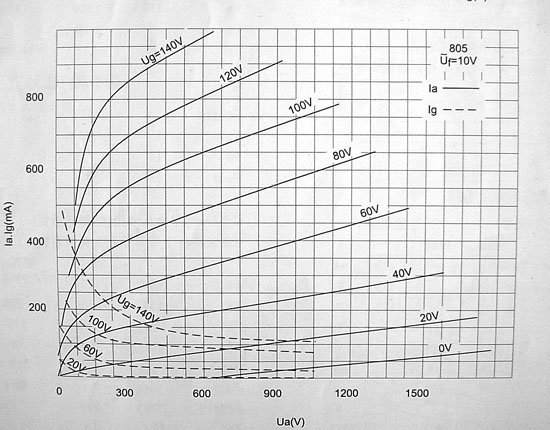
( from the http://www.tube-fullmusic.com/products/en-product0-805.htm )
Y axis = Ia anode current ?
X axis = Ua anode voltage
Curves = Ug grid voltage
update..
perhaps is the axis x more expanded...

bye

Hey-Hey!!!,
My 813 project is comming along. B+ of ~650, U-L at 37.5% thanks to a custom pair of output TX's. They deserve a bit of space... I acquired a Peerless S-271-S, and had it unwound. It is a 2.25" stack of 1.75" EI rated for 80W. It has 8 layers of primary on each side of CT, so I get end-of-layer taps at any multiple of 12.5%, so I'm getting them wound with the first three layers tapped. Stacked with .009" M3.
The circuit is a pentode( or faux pentode cascode ) diff amp. CCS by MOSFET and a E-Linear connection to 25% taps( each half of the diff amp attached to the side of the OPTx that it is feeding the g1 to). Gapped C-core grid choke to side-step the 30k grid circuit limit.
B+ is done LC-LC with 10 Hy and parallel damper diodes and 660vac PIO caps. ~150 mA per 813 idle. With a 5k a-a load, and 37.5% U-L it will still be Class A, and as such ought to deliver me power on par with the output's rating. I can always have another coil wound for additional stacking of Iron if it turns out I need more core area.
cheers,
Douglas
My 813 project is comming along. B+ of ~650, U-L at 37.5% thanks to a custom pair of output TX's. They deserve a bit of space...
I acquired a Peerless S-271-S, and had it unwound. It is a 2.25" stack of 1.75" EI rated for 80W. It has 8 layers of primary on each side of CT, so I get end-of-layer taps at any multiple of 12.5%, so I'm getting them wound with the first three layers tapped. Stacked with .009" M3.The circuit is a pentode( or faux pentode cascode ) diff amp. CCS by MOSFET and a E-Linear connection to 25% taps( each half of the diff amp attached to the side of the OPTx that it is feeding the g1 to). Gapped C-core grid choke to side-step the 30k grid circuit limit.
B+ is done LC-LC with 10 Hy and parallel damper diodes and 660vac PIO caps. ~150 mA per 813 idle. With a 5k a-a load, and 37.5% U-L it will still be Class A, and as such ought to deliver me power on par with the output's rating. I can always have another coil wound for additional stacking of Iron if it turns out I need more core area.
cheers,
Douglas
Hey-Hey!!!,
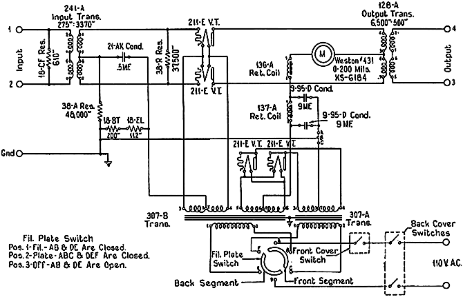
I will direct you to an already published schematic.
http://www.audioroundtable.com/GroupBuild/Projects/Merlin.pdf
That is the nuts an' bolts of it.
cheers,
Douglas
I will direct you to an already published schematic.
http://www.audioroundtable.com/GroupBuild/Projects/Merlin.pdf
That is the nuts an' bolts of it.
cheers,
Douglas
Hey Bandersnatch,
Thanks for the schematic. How do you achieve CCS1 and CCS2 and are they really necessary? It seems like resistors would be o.k. here as well for the bias blocking inductor. I am trying to understand the precise advantages of Douglas Piccard's schematic.
Please post your results when the amp is done. It will be most intersting. I plan to do the same.
Sparky
Hey-Hey!!!,
The common-cathode or 'tail' load is needed( or provide balanced drive to both grids ). You're right about the upper CCS, a resistive voltage divider will do just fine. I'd sugest bypassing the lower resistor with a good cap.
The amp is underway, in a slightly lower power version first. It uses the 4E27A radial pentode from Eimac. This tube shares the 7-pin socket with the 813, so it will get the 813's output installed, and have the filament voltage bumped to 10.
The grid choke is a distinct improvement on straight resistors. Even a very simple wind( dual bay bobbin, one bay reverse wound so that the turns at the CT are next to the core )works. Try it with 1" EI scrappless.
cheers,
Douglas
Hey Bandersnatch,
I would think that it would be a goal not to use any magnetics not necessary to avoid the nonlinear and hysteresis characteristics. (Output transformers are needed because they match high impedance tubes to low impedance speaker voice coils.) In the case of the bias choke, why not just use an interstage transformer? They used to do it all the time. The answer is that electron or cap coupling is linear, wide frequency response, and has no magnetic anomalies, and is therefore better.
On the bias choke, the one advantage I see is that the choke is another stage which enforces push pull symmetry. It is redundant in this task because the preceding differential amplifier alreacy splits the phases.
Have you experienced any peaking or notches due to resonance of the choke with the series coupling capacitor.
Also, why is this a gapped choke? Why not a minimum gap transformer type core?
I am a newbie to audio, and I have to analyze these designs to the best of my ability. Sincere thanks for your help. I am really having fun with the 813 breadboard.
Sparky
sparky813 said:Hey Bandersnatch,
I would think that it would be a goal not to use any magnetics not necessary to avoid the nonlinear and hysteresis characteristics. (Output transformers are needed because they match high impedance tubes to low impedance speaker voice coils.) In the case of the bias choke, why not just use an interstage transformer? They used to do it all the time. The answer is that electron or cap coupling is linear, wide frequency response, and has no magnetic anomalies, and is therefore better.
On the bias choke, the one advantage I see is that the choke is another stage which enforces push pull symmetry. It is redundant in this task because the preceding differential amplifier alreacy splits the phases.
Have you experienced any peaking or notches due to resonance of the choke with the series coupling capacitor.
Also, why is this a gapped choke? Why not a minimum gap transformer type core?
I am a newbie to audio, and I have to analyze these designs to the best of my ability. Sincere thanks for your help. I am really having fun with the 813 breadboard.
Sparky
The load on the front end has to be resistive as far as I can tell. It is a fairly low value, at ~10k. The grid choke takes good care of the 813's grid circuit resistance spec.
The gap is used because the average perm of the gap and the core is a lot more consistent than a minimum gap. In short, I have found that it sounds better. SE amps have a nice gap in their outputs, and I think it contributes to their usual difference in sound v. PP amps. I have not found any resonances, though I do use a rather large coupling cap at 1.5-2 uF.
Anyway, I have been playing with an ampof this topology for a few years now. I do like it's performance, and I am itching to scale it up and see how it works. The 5-125B/4E27A is very convenient step on the way to using the 813...
The 5-125B amp is running a 10k a-a output, the Peerless S-265-Q wound with taps at 20, 30 and 40% along the anode winding. It worked well for me, and they're very reasonably priced at ~$100 each!cheers,
Douglas
Hey Bandersnatch,
Do you know the reason for the 813 spec of 30kohms maximum grid 1 resistance? I notice that there is a resistance spec for most pentodes, but not for triodes or tetrodes, in the RCA Transmitting Tube manual. Do you know if the 30k is for dc resitance, bias stability reasons, or a dynamic requirement? The 813 is so easy to drive, using almost no power for class A. I have 100k right now on my breadboard, which is only running 600v on the plates and has cathode bias. It seems fine. I always tell everyone else to study and understand every footnote and line item of a spec. I guess its time for me to take my own medicine.
Sparky
sparky813 said:Hey Bandersnatch,
Do you know the reason for the 813 spec of 30kohms maximum grid 1 resistance? I notice that there is a resistance spec for most pentodes, but not for triodes or tetrodes, in the RCA Transmitting Tube manual. Do you know if the 30k is for dc resitance, bias stability reasons, or a dynamic requirement? The 813 is so easy to drive, using almost no power for class A. I have 100k right now on my breadboard, which is only running 600v on the plates and has cathode bias. It seems fine. I always tell everyone else to study and understand every footnote and line item of a spec. I guess its time for me to take my own medicine.
Sparky
The bias circuit resistance is for bias stability reasons. Note that the difference between the fixed bias spec and cathode bias is ~1:5 ( with fixed bias being lower ).
Cheers,
Douglas
sparky813 said:Hey Bandersnatch,
Do you know the reason for the 813 spec of 30kohms maximum grid 1 resistance? I notice that there is a resistance spec for most pentodes, but not for triodes or tetrodes, in the RCA Transmitting Tube manual. Do you know if the 30k is for dc resitance, bias stability reasons, or a dynamic requirement? The 813 is so easy to drive, using almost no power for class A. I have 100k right now on my breadboard, which is only running 600v on the plates and has cathode bias. It seems fine. I always tell everyone else to study and understand every footnote and line item of a spec. I guess its time for me to take my own medicine.
Sparky
I used to wonder about the 30k limit for grid leaks. I generally used 47k which I always felt was a "nice" sort of value for a grid leak.
I imagine that like many big valves 813 could perhaps be a bit gassy. One I did a lot of work with was 13E1; these could be very gassy indeed and it was necessary to warm them up out gas them.
Meanwhile, there was mention of antique electronics - I found this on my computer which may appeal!
An externally hosted image should be here but it was not working when we last tested it.
[/URL][/IMG] 
Paul
EDIT: Sorry it's so small - I cannot make it any bigger despite three attempts - grrrrrrr
This is supposed to be a link...
http://img80.imageshack.us/img80/5964/bignj4.jpg
http://img80.imageshack.us/img80/5964/bignj4.jpg
Hi Paul,
I certainly do not know why the 30k limit for the 813 G1. I suspect that this limit may be more important when the tube is running maximum plate voltage or slightly positive G1 voltage peaks where grid current is drawn. When us audio experimenters use the 813's at 600v or 900v on the plate, the 30k may not matter as much. I used 100k on my breadboard and it works fine. I changed to 25k with no differences observed.
Triodes may not need this spec because they must already be driven from lower impedance sources.
On a personal note, my shop just flooded in the Western Washington flood last week with six feed of water in my shop. The nice 24" swing engine lathe I just used to wind my output transformer was a casualty. I saved all my paperwork on the transformer design just in the nick of time. The flood is devastating to me, but just for material things, like my business. Many others have lost their homes or lives ( 2 deaths I think) I am not looking for sympathy, but anyone thinking about locating near a river should think twice about it.
Sparky
Sparky,
So sorry to hear about the disaster; it is dreadful to lose treasured tools and parts. As you say, it could have been worse...
I imagine that you are correct with regard to the 30k and our "low" voltages; after all, with 2kV on the anode and 600V on G2, I suppose things could be a bit more "testing".
Paul
955s - off topic!
Sparky,
regarding the acorns, I have located my test results (for distortion). These included a lot of single valve tests as well as some for differential pairs.
The results were interesting. Unfortunately, they are on Excel files which I do not think that I can post up here. I might try to open a Google page and attach a link, unless someone has a better idea?
Paul
Sorry to hear about your flood situation. If your experiences are anything like mine, you will have electronics failing for the next year or two. Even things that didn't appear to get wet. Vacuum tube transformers seem to absorb the moisture like sponges, then fry later. I have some name brand OPT's that have rust all over the cores, and they never got wet. There was no rust on them until the hurricane, now 1 year later they are all brown.
The value given for the maximum grid resistor is to take care of gassy tubes that draw some grid current. You can get away with pushing the value on some tubes, but you will eventually find one that will go into a runaway condition when it gets hot. This is worse with fixed bias, and some tubes are worse than others. I have seen NOS Sylvania 6550's run away (severe red plate) after an hour of operation with a 120K resistor and cathode bias. The max spec is 250K. Oddly enough the Sovteks, EH's and the others that I have tried are happy with 220K. The runaway comes up quickly, the amp was playing fine, and I started to notice a small hum in one channel, within 1 minute the tube was glowing bright red. The cathode resistor was smoking hot. 6550's have a reputation for this, at least they did when I worked in a stereo shop 35 years ago.
All tubes will have trouble if the grid circuit resistance is too high. Many transmitting triodes were intended to operate in the grid current region, which assumed a low resistance driver, usually a trasnformer. Many small signal tubes used the grid resistor to develop bias by leaking off some of the space charge. This was known as grid leak bias. Values up to 5 megohms were common. This is not used today because of the wide variation in tubes.
- Status
- This old topic is closed. If you want to reopen this topic, contact a moderator using the "Report Post" button.
- Home
- Amplifiers
- Tubes / Valves
- transmitter tube amp